

Display device and display method
a technology of display device and display method, which is applied in the direction of waveguide, waveguide type device, instrument, etc., can solve the problems of low light utilization efficiency, inability to use as a projection display, and inability to realize high contrast, etc., and achieve high light utilization efficiency and high contrast
- Summary
- Abstract
- Description
- Claims
- Application Information
AI Technical Summary
Benefits of technology
Problems solved by technology
Method used
Image

Examples
first embodiment
[0097]FIG. 9 is a perspective view schematically showing a controller 4 of a display device 1 according to the present invention. This controller 4 shown in FIG. 9 has a transparent electrode 15 formed on a transparent substrate 2 as a transparent base, a plate-like transparent member 17 opposing the transparent substrate 2 with a predetermined distance between them, a beam (cantilever) 18 formed on the transparent substrate 2 to support one end of the transparent member 17, a transparent electrode 16 formed on the side of the transparent member 17 away from the transparent substrate 2, and a total reflection preventing member 19 formed on the transparent electrode 16. The transparent electrode 15, the cantilever 18, and the transparent electrode 16 constitute a moving mechanism. Lines 20 and 21 are formed on the transparent substrate 2 and connected to the transparent electrodes 15 and 16, respectively. The operation of the controller 4 shown in FIG. 9 will be described below with ...
second embodiment
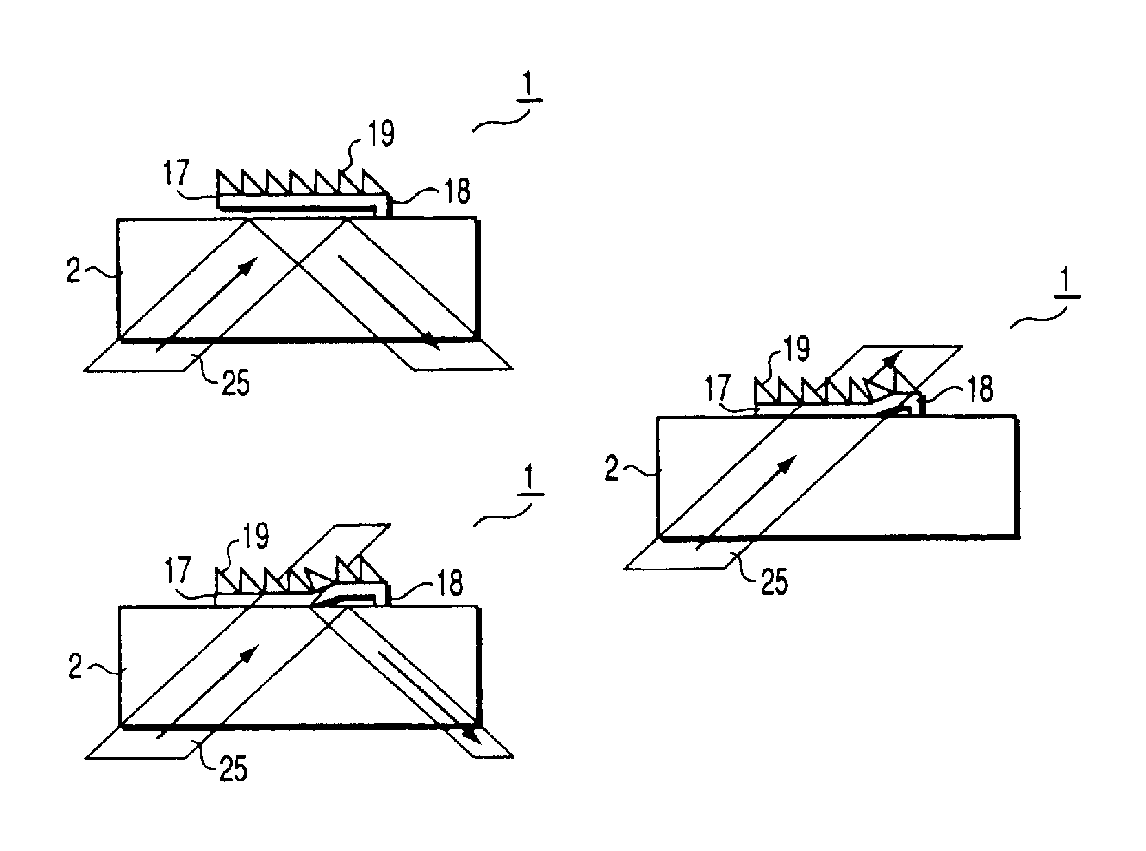
[0129]FIG. 16 is a perspective view schematically showing a controller 4 of a display device 1 according to the present invention. This controller 4 shown in FIG. 16 includes a transparent electrode (not shown) formed on a light transmitting member 2, a plate-like transparent member (not shown) opposing the light transmitting member 2 with a predetermined distance between them, a beam 18 formed on the light transmitting member 2 to support the periphery of the transparent member, a transparent electrode 16 formed on the surface of the transparent member away from the light transmitting member 2, and a total reflection preventing member 19 formed on the transparent electrode 16. Also, lines 20 and 21 are formed on the light transmitting member 2 and connected to the two transparent electrodes described above. The operation of the controller 4 shown in FIG. 16 will be described below with reference to FIGS. 17A and 17B.
[0130]FIGS. 17A and 17B are side views schematically showing the d...
third embodiment
[0135]FIG. 18 is a perspective view schematically showing the transparent member 17 of a display device 1 according to the present invention. A plurality of tapered projections are arrayed on that surface of the transparent member 17 shown in FIG. 18, which faces the light transmitting member 2. This transparent member 17 is made from an elastic material having a small elastic coefficient, such as silicone resin or polycarbonate. Therefore, these projections are deformable. The operation of a controller 4 having the transparent member 17 shown in FIG. 18 will be described below with reference to FIGS. 19A to 19C.
[0136]FIGS. 19A to 19C are side views schematically showing the display device 1 according to the third embodiment of the present invention. FIG. 19A shows the state in which no voltage is applied between transparent electrodes. In this state, the transparent member 17 and a transparent electrode formed on the light transmitting member 2 are spaced apart from each other. Sin...
PUM
 Abstract
Description
Claims
Application Information