
Minimizing power consumption in pipelined circuit by shutting down pipelined circuit in response to predetermined period of time having expired

a pipelined circuit and power consumption technology, applied in the field of power management techniques for computer chips, can solve the problems of reducing the efficiency of pipelined circuits, so as to reduce the power consumption and minimize the step-load

Inactive Publication Date: 2005-06-14
HEWLETT-PACKARD ENTERPRISE DEV LP
View PDF13 Cites 22 Cited by
  • Summary
  • Abstract
  • Description
  • Claims
  • Application Information

AI Technical Summary

Benefits of technology

The present invention provides a method and circuit for minimizing power consumption in a pipelined circuit. The method involves detecting a predetermined period of time has passed and shutting down the circuit to reduce power consumption. The circuit includes a first transition detection circuit, a second transition detection circuit, and a stage control circuit that controls power consumption based on a signal received from either the first or second transition detection circuit. The circuit can also include an arbitration circuit for generating signals to control power provided to the pipelined circuit. The invention reduces power consumption and minimizes a step-load effect caused by an instant shut-down or power-up of an entire pipelined circuit.

Problems solved by technology

However, high-performance pipeline stage circuits often substantially dissipate power when performing calculations.
Even when functioning in an idle or sleep mode, conventional pipeline stage circuits dissipate a significant amount of power through leakage paths.
Techniques utilizing a sleep mode, however, tend to suffer from step-load problems.
These problems result from an inductive effect in a power delivery line for the pipeline stage circuits.
This results in a step-load effect.
Enlarging the on-chip decoupling capacitance, however, has not proved feasible for a variant demand for power during chip operation.
Also, executing a dummy cycle tends to waste a considerable amount of power.

Method used


Image

  • Minimizing power consumption in pipelined circuit by shutting down pipelined circuit in response to predetermined period of time having expired
  • Minimizing power consumption in pipelined circuit by shutting down pipelined circuit in response to predetermined period of time having expired
  • Minimizing power consumption in pipelined circuit by shutting down pipelined circuit in response to predetermined period of time having expired

Examples


Embodiment Construction

[0016]In the following detailed description, numerous specific details are set forth in order to provide a thorough understanding of the present invention. However, it will be apparent to one of ordinary skill in the art that these specific details need not be used to practice the present invention. In other instances, well known structures, interfaces, and processes have not been shown in detail in order not to unnecessarily obscure the present invention.

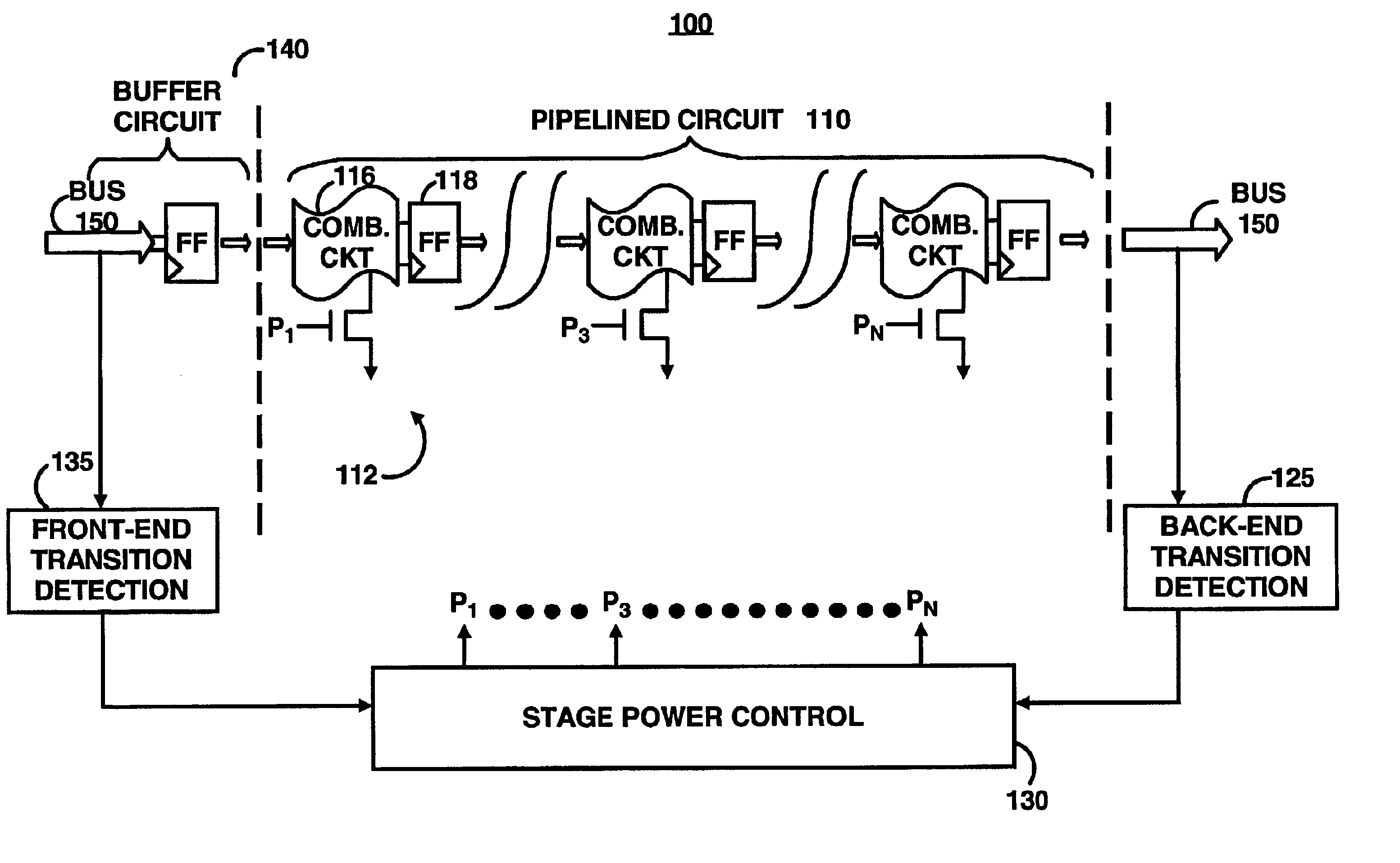
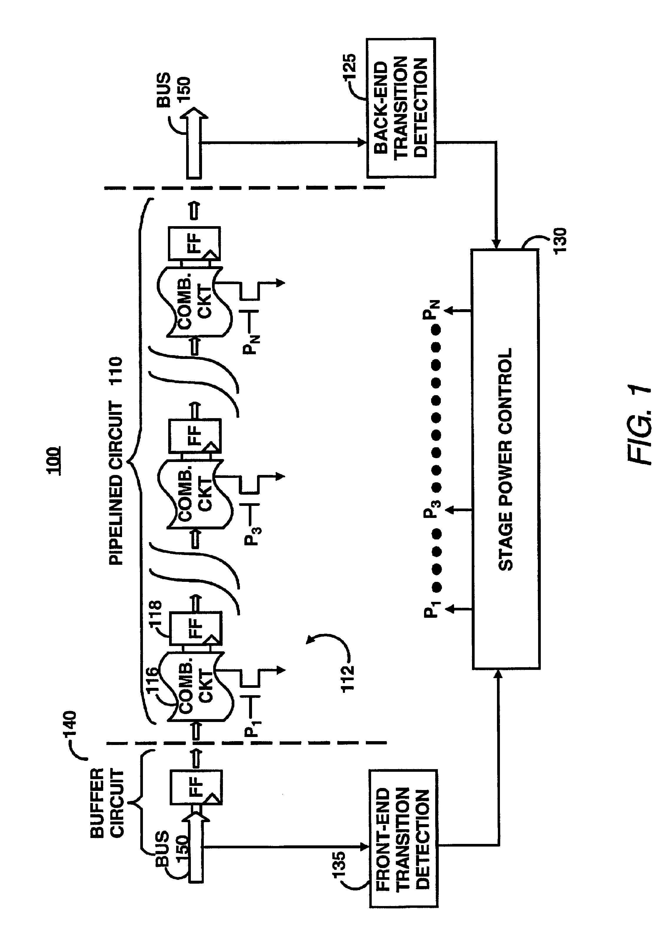
[0017]“FIG. 1 illustrates a power control circuit 100 managing power consumption and power delivery to a pipelined circuit 110. The pipelined circuit 110 includes multiple stage circuits 112, each of which includes a power switch PN, conventional combinational logic circuitry 116 and a flip-flop 118. The flip-flop 118 may be a conventional flip-flop or a power saving flip-flop described in co-pending U.S. patent application Ser. No. 09 / 941,581 herein incorporated by reference.”

[0018]The power control circuit 100 includes a back-end...


PUM


Abstract

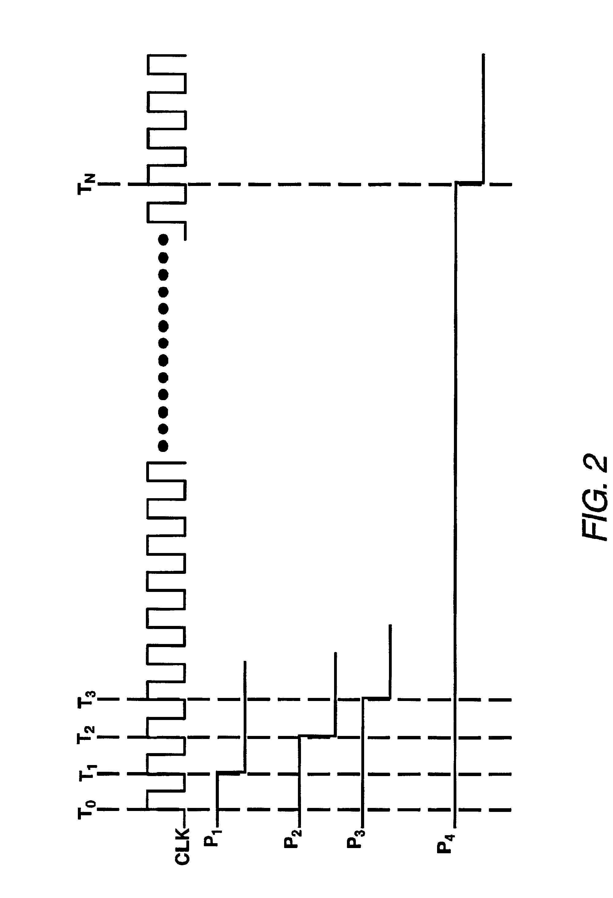
Power consumption in a circuit is minimized. The circuit includes a pipelined circuit having a plurality of stages. A determination is made as to whether a predetermined period of time has expired. The predetermined period of time being associated with a predetermined period of time to detect a transition of an input or an output of the pipelined circuit. If the predetermined period of time is exceeded, a sequential shut-down procedure is performed on each stage in the plurality of stages of the pipelined circuit so that each stage is shut-down.

Description

FIELD OF THE INVENTION[0001]The present invention is generally related to power management techniques for computer chips. More particularly, the present invention is generally related to reducing power consumption of a pipelined circuit in a computer chip.BACKGROUND OF THE INVENTION[0002]In a typical microprocessor chip, designers often use a pipelined circuit to perform certain operations, such as floating point computations, for increasing the chip's frequency. A pipelined circuit conventionally includes multiple pipeline stage circuits for performing the computations. Conventional pipeline stage circuits are often modified to increase the performance of the chip. However, high-performance pipeline stage circuits often substantially dissipate power when performing calculations. Even when functioning in an idle or sleep mode, conventional pipeline stage circuits dissipate a significant amount of power through leakage paths.[0003]With the ever increasing demand for power in micropro...

Claims


Application Information

Patent Timeline
Patent Type & Authority Patents(United States)
IPC IPC(8): G06F1/32G06F9/38
CPCG06F9/3869G06F1/3203
Inventor KU, JOSEPH
Owner HEWLETT-PACKARD ENTERPRISE DEV LP
Learn More