Fuel tank assembly

a technology for fuel tanks and assembly parts, which is applied in the direction of liquid fuel feeders, machines/engines, and feeding systems of small recreational vehicles. it can solve the problems of increasing the noise of the pump, difficult to introduce the sub-assembly of the fuel pump inside the tank of such a small recreational vehicle, and difficulty in pump placement, so as to prolong the operational life of the fuel pump. the effect of reducing noise, reducing vibration amplitude, and reducing the length of the fuel

Inactive Publication Date: 2005-06-21
WALBRO ENGINE MANAGEMENT
View PDF16 Cites 54 Cited by
  • Summary
  • Abstract
  • Description
  • Claims
  • Application Information

AI Technical Summary

Benefits of technology

[0007]Objects, features, and advantages of this invention include a fuel tank assembly for a fuel injected engine application which maintains traditional fuel tank exterior appearance, a reduction in fuel hose a

Problems solved by technology

Unfortunately, the introduction of a fuel pump subassembly inside the tank of such a small recreational vehicle is difficult because: the fuel tank is visually exposed and typically mounted near the top of the recreational vehicle making cosmetic appearance and thus the location of the pump subassembly flange a concern; the tank is relatively small making pump placement difficult; and the tank is typically made of metal which contributes to the proliferation of pump noise.
Often, the shape or general appearance of the tank is identifiable to a particular manufacturer, thus having trademark value, thus making cosmetic alterations for the addition of a fuel pump subassembly undesirable.
However, the cap is relatively low and smooth in profile and is located toward the forward top of the tank at

Method used


Image

  • Fuel tank assembly
  • Fuel tank assembly
  • Fuel tank assembly

Examples


Embodiment Construction

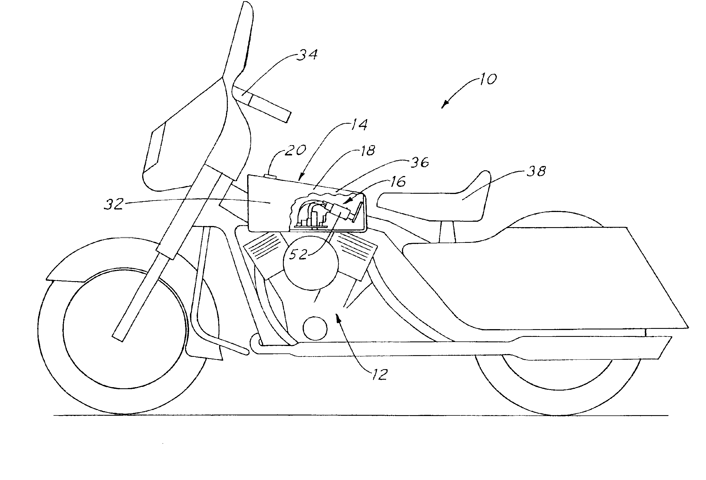
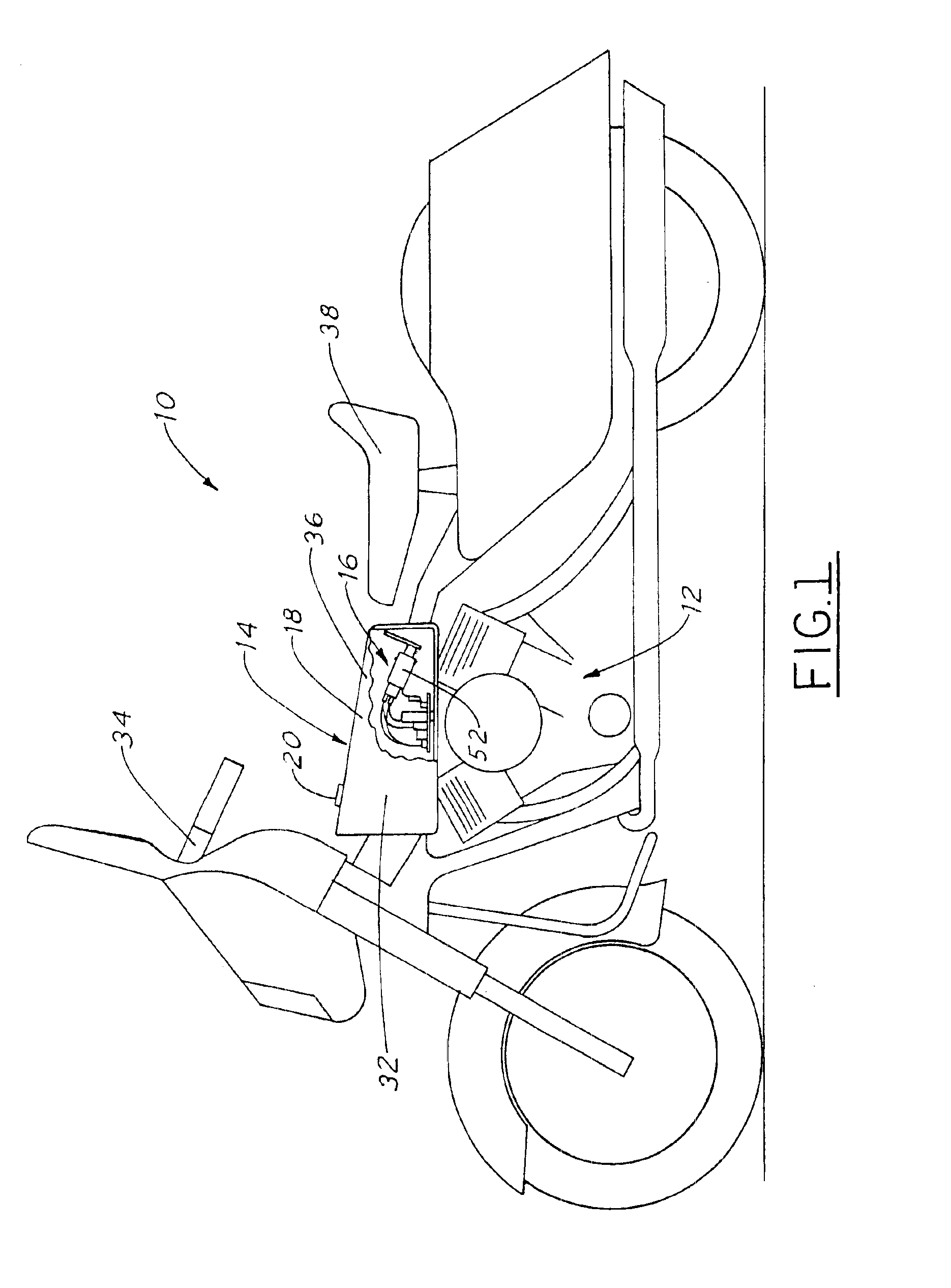
[0016]Referring to FIG. 1, a motorcycle 10 has a fuel injected engine 12 which receives pressurized fuel from a cosmetically attractive fuel tank assembly 14. A fuel pump subassembly 16 of the fuel tank assembly 14 is conveniently concealed inside a fuel tank 18 of the assembly 14 thus preserving the aesthetic appearance, shape and any trademark value pre-established by the manufacturer. The only exposed or viewable component of the fuel tank 18 is a conventional top mounted filler cap 20, thus the tank 18 appears like a conventional fuel tank, however, the tank 18 of the present invention is not limited to flowing fuel via gravity to a combustion engine utilizing old carburetor technology.

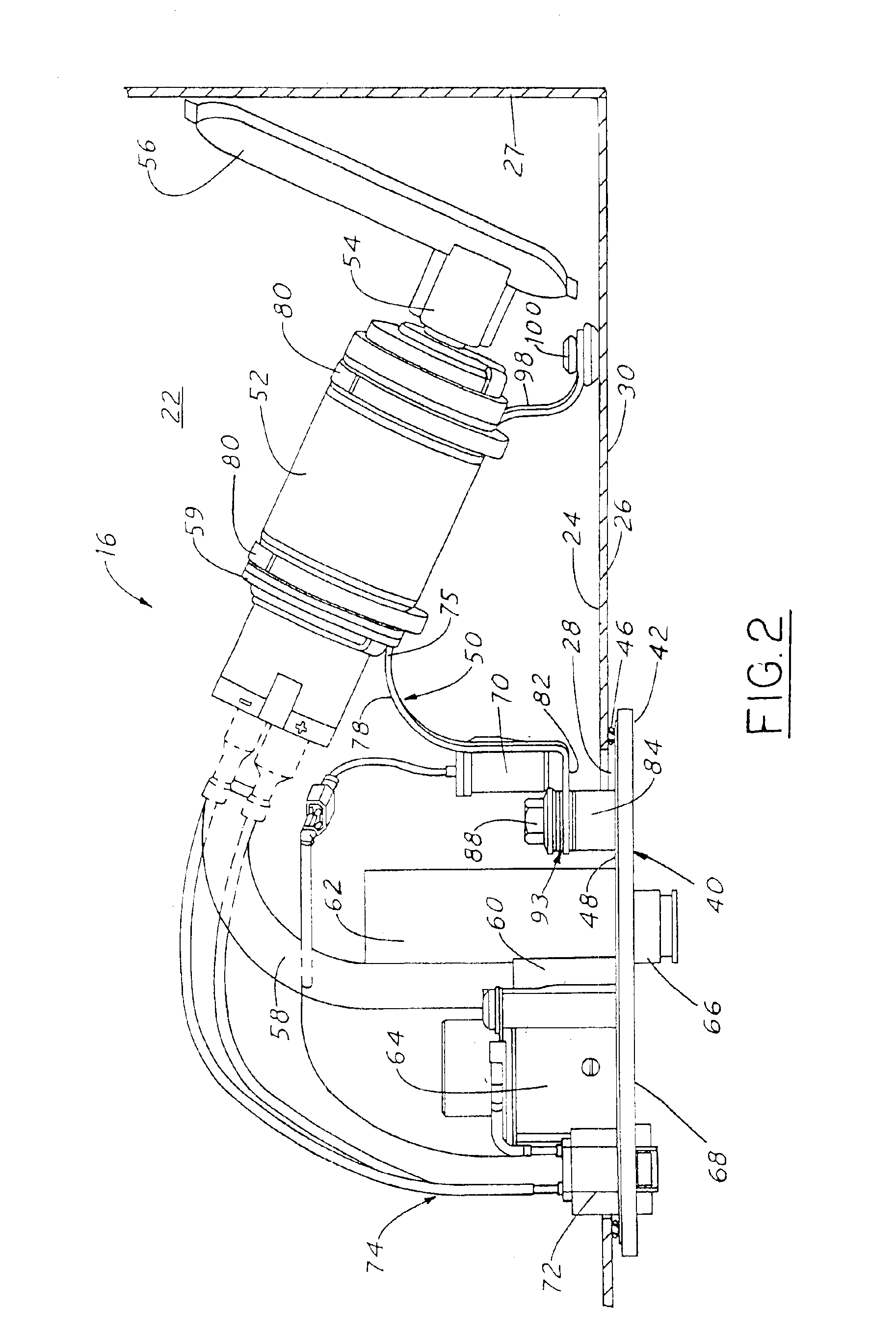
[0017]Referring to FIGS. 1-3, the fuel tank 18 of the present invention is preferably made of metal for structural strength and superior paint adherence for cosmetic purposes. The fuel pump subassembly 16 is generally elongated in a non-linear fashion and shaped to fit within the relatively small ...


PUM


Abstract

A cosmetically attractive fuel tank assembly preferably for a motorcycle application has a fuel pump subassembly inserted into the fuel chamber of the tank through bottom access hole thus preserving the overall appearance of the tank itself. The flange of the fuel pump subassembly covers the bottom access hole and sealably months to a bottom wall of the fuel tank. Various fuel pump subassembly components, such as a fuel pressure regulator, an outlet fuel filter, an electrical connector and a fuel outlet mount directly to the flange along with a tripod like vibration absorbing bracket which supports the fuel pump and preferably a fuel level sensor. The bracket is flexible and resiliently contacts an internal surface of a bottom wall of the fuel tank via a resilient pad, and is threadably engaged to the flange and spaced therefrom by a vibration damping member.

Description

TECHNICAL FIELD[0001]The present invention relates to a fuel tank assembly and more particularly to a fuel pump subassembly of the fuel tank assembly for a motorcycle.BACKGROUND OF THE INVENTION[0002]Large vehicles, such as the automobile, have a typically fuel injected engine and a fuel pump subassembly mounted inside a fuel tank. The fuel tank is generally hidden from view and mounted to the undercarriage of the vehicle. Various penetrations and protrusions, such as a tank access hole for insertion of the fuel pump subassembly into the tank, are typically located at the top of the tank to minimize any opportunity of fuel leakage. A top mounted flange supports the fuel pump subassembly and covers and seals the access hole. Location of the flange and various protrusions projecting outward from the flange at the top of the tank protects the flange from abusive road conditions. Because the tanks are concealed by the undercarriage of the vehicle, any negative cosmetic impact of the top...

Claims


Application Information

Patent Timeline
IPC IPC(8): F02M37/10F02M37/08F02B61/02F02B61/00F02M37/22
CPCF02M37/103F02B61/02F02M2037/228F02M37/50
Inventor HANBY, JEFFREY D.
Owner WALBRO ENGINE MANAGEMENT
Why Eureka
Try Eureka