Ignition timing control system and method for variable-cylinder internal combustion engine as well as engine control unit

a technology of ignition timing control system and control unit, which is applied in the direction of electric control, ignition automatic control, instruments, etc., can solve the problems of reducing torque, reducing torque, and reducing output torque per cylinder, so as to reduce shock and optimize torque.

Active Publication Date: 2005-06-21
HONDA MOTOR CO LTD
View PDF2 Cites 15 Cited by
  • Summary
  • Abstract
  • Description
  • Claims
  • Application Information

AI Technical Summary

Benefits of technology

[0008]It is an object of the present invention to provide an ignition timing control system and method for a variable-cylinder internal combustion engine as well as an engine control unit, which are capable of optimally reducing torque before the start of fuel cut-off operation, irrespective of whether the engine is in an all-cylinder operation mode or in a partial-cylinder operation mode, thereby reducing shock caused by the fuel cut-off operation.

Problems solved by technology

However, when the ignition timing control system is applied to the variable-cylinder internal combustion engine, there occurs the following problem: In the partial-cylinder operation mode, since part of the cylinders are deactivated, output torque per cylinder tends to be larger than in the all-cylinder operation mode, on condition that the same torque is output by the whole engine.
As a result, when the deceleration operating conditions are satisfied, if the engine is in the partial-cylinder operation mode, it is impossible to reduce the torque sufficiently even though the ignition timing is retarded by the above method, and hence there is a fear of a sudden reduction of torque at the start of the fuel cut-off operation causing a large toque shock.
However, if the engine is in the all-cylinder operation mode when the deceleration operating conditions are satisfied, the output torque per cylinder is so small that the ignition timing retarded using the amount of retardation set as above reduces the torque more than required, resulting in occurrence of shock or low rotational speed of the engine.

Method used


Image

  • Ignition timing control system and method for variable-cylinder internal combustion engine as well as engine control unit
  • Ignition timing control system and method for variable-cylinder internal combustion engine as well as engine control unit
  • Ignition timing control system and method for variable-cylinder internal combustion engine as well as engine control unit

Examples


Embodiment Construction

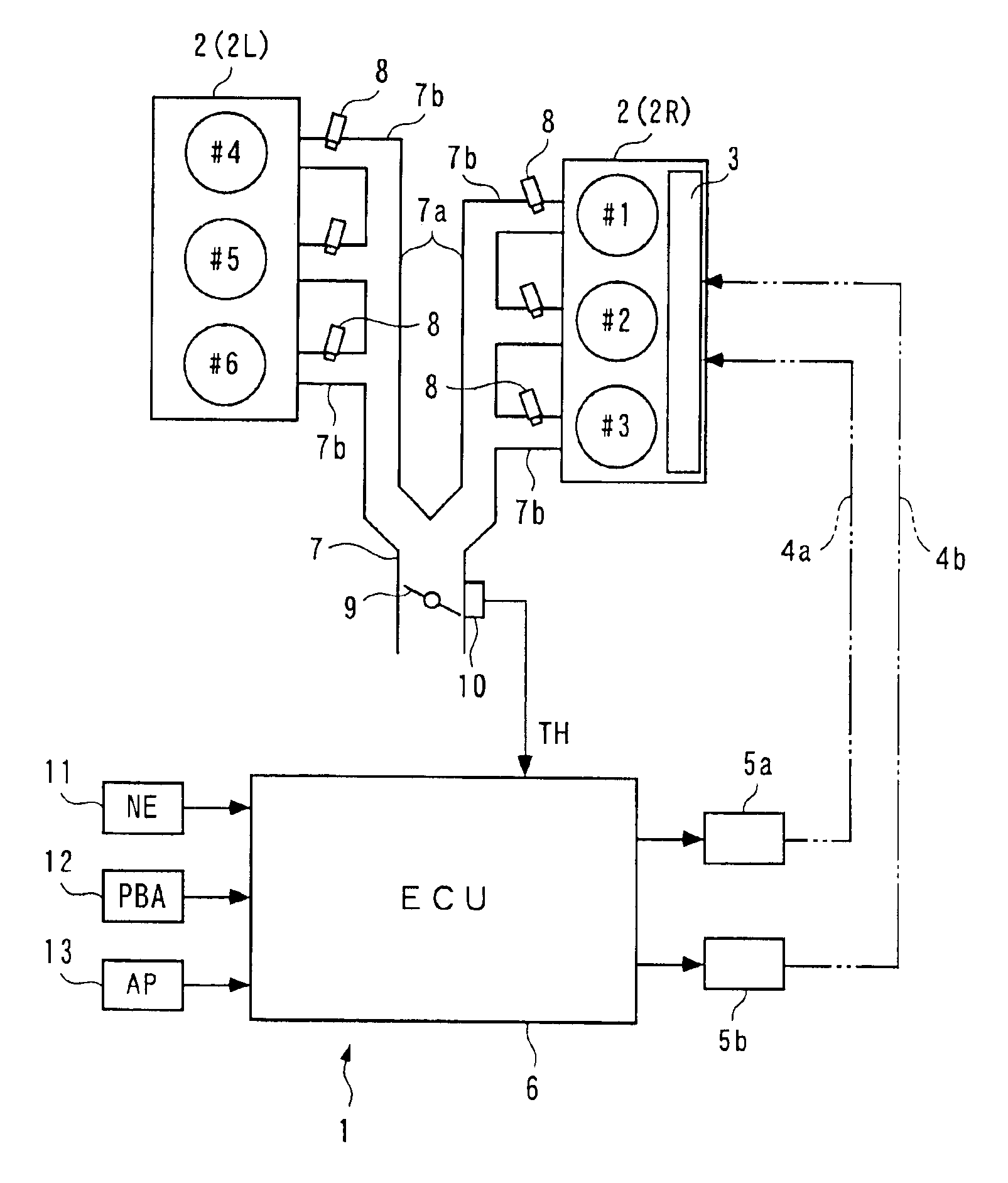
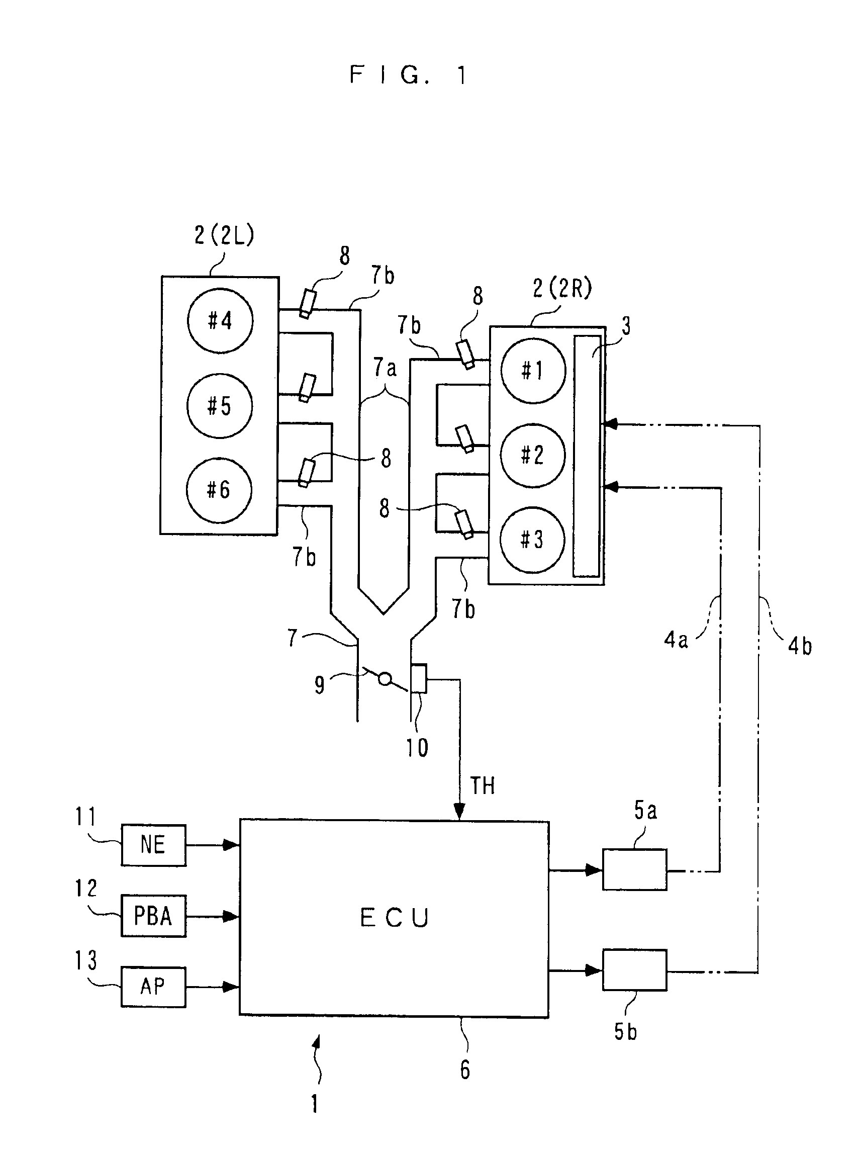
[0047]The present invention will now be described in detail with reference to the drawings showing a preferred embodiment thereof. Referring first to FIG. 1, there is schematically shown the arrangement of a variable-cylinder internal combustion engine 2 to which is applied an ignition timing control system 1 according to the embodiment of the present invention. This variable-cylinder internal combustion engine 2 (hereinafter simply referred to as “the engine 2”) is a V type six-cylinder DOHC gasoline engine installed on a vehicle, not shown.

[0048]As shown in the figure, the engine 2 includes a right bank 2R of three cylinders #1, #2, and #3, and a left bank 2L of three cylinders #4, #5, and #6. The engine 2 is operated while switching the operation mode thereof between an all-cylinder operation mode and a partial-cylinder operation mode. Further, the right bank 2R is provided with a cylinder-deactivating mechanism 3 for carrying out the partial-cylinder operation mode.

[0049]The cyl...


PUM


Abstract

There is provided an ignition timing control system for a variable-cylinder internal combustion engine, which is capable of optimally reducing torque before the start of fuel cut-off operation, irrespective of whether the engine is in an all-cylinder operation mode or a partial-cylinder operation mode, thereby reducing shock caused by the fuel cut-off operation. When the internal combustion engine is operated under deceleration operating conditions, the start of cut-off of fuel supply is delayed for a predetermined time period, and ignition timing is corrected when the cut-off of fuel supply is being delayed for the predetermined time period. The amount of correction of the ignition timing is set to a different value depending on the operation mode.

Description

BACKGROUND OF THE INVENTION[0001]1. Field of the Invention[0002]The present invention relates to an ignition timing control system and method for a variable cylinder internal combustion engine which is operated by switching an operation mode thereof between an all-cylinder operation mode in which all of a plurality of cylinders are operated, and a partial-cylinder operation mode in which part of the plurality of cylinders are deactivated, as well as an engine control unit.[0003]2. Description of the Prior Art[0004]Conventionally, an ignition timing control system for a variable-cylinder internal combustion engine has been proposed e.g. in Japanese Laid-Open Patent Publication (Kokai) No. H10-30477 (FIG. 1, pages 3 and 4). This engine is not of the above variable-cylinder type but of a normal type. In the engine, when an idle switch is ON, i.e. when a throttle valve is in a substantially fully-closed state, and at the same time the rotational speed of the engine is equal to or higher...

Claims


Application Information

Patent Timeline
Patent Type & Authority Patents(United States)
IPC IPC(8): F02D37/00F02D41/12F02D17/00F02D37/02F02D17/02F02D41/32F02D41/36F02D13/06F02P5/15F02D41/00F02D41/02F02D45/00
CPCF02D13/06F02D17/02F02D37/02F02D41/123F02D41/0087Y02T10/18F02D2250/21F02P5/1504Y02T10/12
Inventor FUKUSAKO, TAKAAKIICYOUDA, TOSHIAKI
Owner HONDA MOTOR CO LTD
Why Eureka
Try Eureka