Driving force distribution control device and driving force distribution method for four-wheel drive vehicle

a technology of driving force distribution control and four-wheel drive, which is applied in the direction of control devices, driver input parameters, and compacts, etc., can solve the problems of frequent change of vehicle behavior and impaired ride quality

Inactive Publication Date: 2005-06-21
JAPAN SCI & TECH CORP +1
View PDF12 Cites 19 Cited by
  • Summary
  • Abstract
  • Description
  • Claims
  • Application Information

AI Technical Summary

Benefits of technology

[0007]An object of the present invention is to provide a driving force distribution control apparatus and driving force distribution method for a four-wheel drive vehicle, in which excessive change of torque distribution can be inhibited.

Problems solved by technology

When the torque distribution mode is frequently switched in this manner, vehicle behavior change frequently occurs (switch shock), and ride quality is impaired.

Method used


Image

  • Driving force distribution control device and driving force distribution method for four-wheel drive vehicle
  • Driving force distribution control device and driving force distribution method for four-wheel drive vehicle
  • Driving force distribution control device and driving force distribution method for four-wheel drive vehicle

Examples


first embodiment

[0018]the present invention will hereinafter be described with reference to FIGS. 1 to 4.

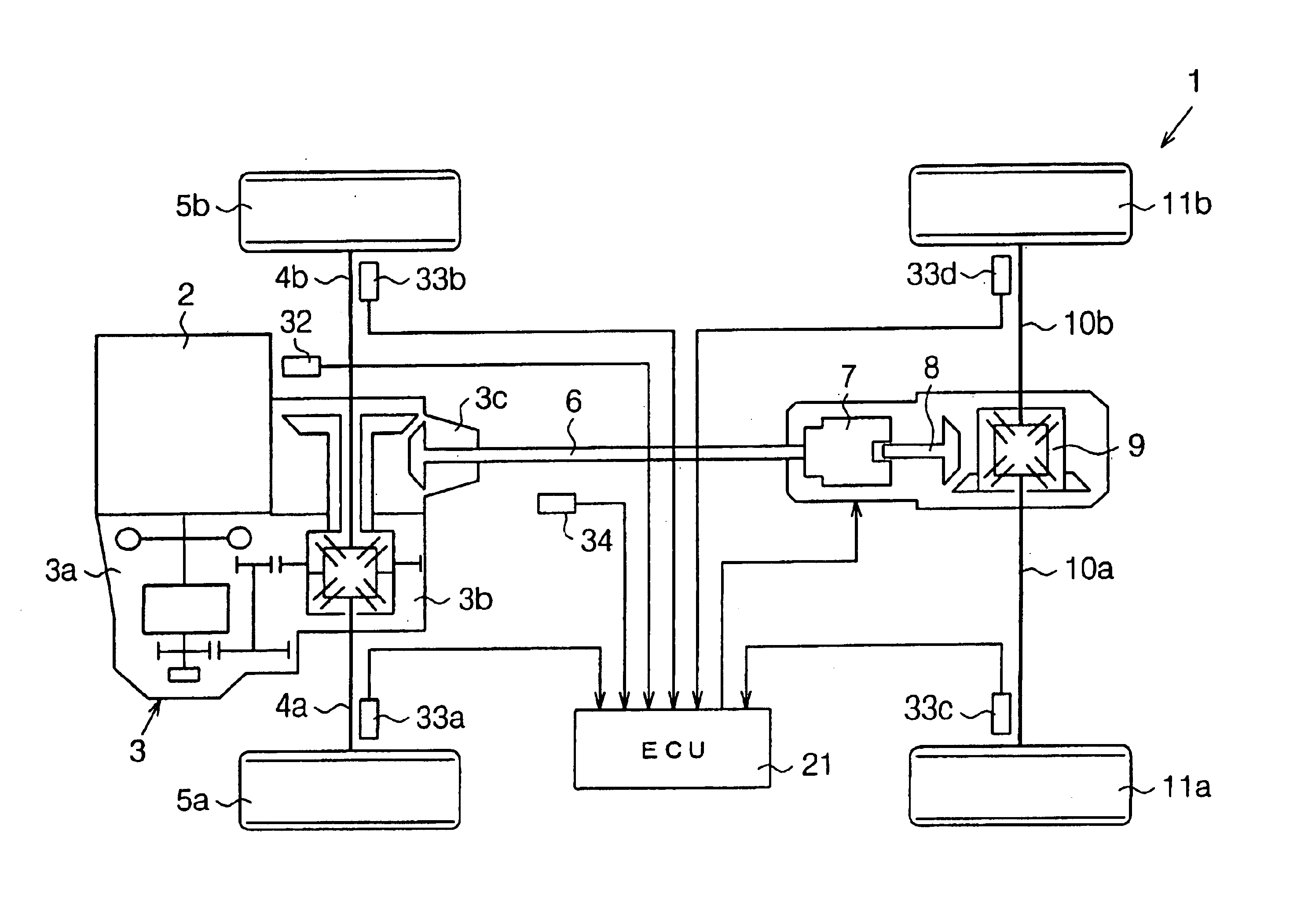
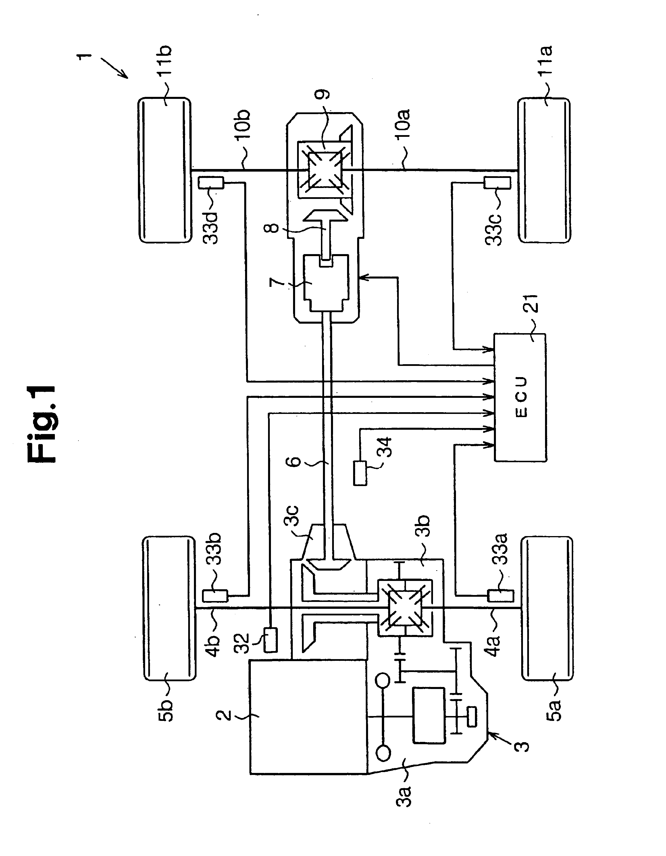
[0019]As shown in FIG. 1, a four-wheel drive vehicle 1 includes an internal combustion engine 2 which is a drive source, and a transaxle 3. The transaxle 3 includes a transmission 3a, front differential 3b, and transfer 3c. The front differential 3b is coupled to a pair of front axles 4a, 4b. One pair of front axles 4a, 4b are coupled to left and right front wheels 5a, 5b, respectively.

[0020]The driving force of the internal combustion engine 2 is transmitted to the front wheels 5a, 5b via the transmission 3a, front differential 3b, and one pair of front axles 4a, 4b.

[0021]The transfer 3c is coupled to a propeller shaft 6, and the propeller shaft 6 is coupled to a coupling 7. Therefore, the driving force (torque) of the internal combustion engine 2 is transmitted to the coupling 7 via the transmission 3a, transfer 3c, and propeller shaft 6. The coupling 7 is coupled to a rear differential 9 via...

second embodiment

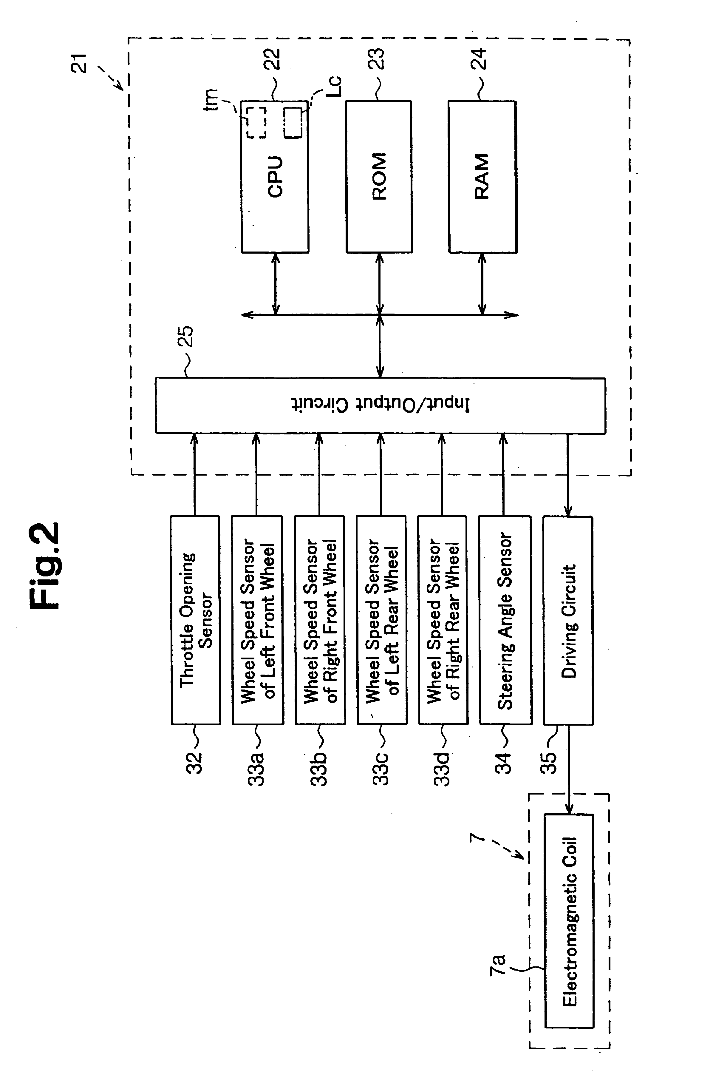
[0057]A second embodiment embodying the present invention will hereinafter be described with reference to FIGS. 5 to 7. It is to be noted that an apparatus constitution of the four-wheel drive vehicle 1 including the ECU 21 of the present embodiment is the same as that of the embodiment of FIGS. 1 to 4, and only the control program for the torque distribution is different from that of the embodiment of FIGS. 1 to 4.

[0058]In the present embodiment, the timer counts the time counter tm indicating a time from when either of the throttle opening determination flag and the steering angle determination flag is set. The initial value of the time counter tm is set to 0.

[0059]FIGS. 5 and 6 are flowcharts of a mode switch control program processed by the CPU 22 by the regular interrupt.

[0060]In steps S201 and S202, the CPU 22 performs the process similar to that of steps S101 and S102 in FIG. 3.

[0061]Next, in step S203, the CPU 22 determines whether or not either of the throttle opening deter...


PUM


Abstract

An ECU, which functions as a driving force distribution control apparatus for a four-wheel drive vehicle, includes a CPU. The CPU controls a coupling for changing torque distribution of front and rear wheels. The CPU determines either of first and second torque distribution modes based on detection signals of a throttle opening sensor and steering angle sensor, which are operating parameters. In the second torque distribution mode, torque is distributed to the front and rear wheels more equally than in the first torque distribution mode. The CPU sets a duration for the second torque distribution mode when the second torque distribution mode is selected. Until the duration elapses, regardless of the operating parameters, the CPU continues the control of the coupling in the second torque distribution mode.

Description

CROSS-REFERENCE TO RELATED APPLICATIONS[0001]This application is based upon and claims the benefit of priority from prior Japanese patent application number 2002-126224, filed Apr. 26, 2002, the entire contents of which are incorporated herein by reference.FIELD OF THE INVENTION[0002]The present invention relates to a driving force distribution control apparatus and driving force distribution method for a four-wheel drive vehicle.BACKGROUND OF THE INVENTION[0003]A driving system for a four-wheel drive vehicle includes: a part-time driving system for appropriately switching between four-wheel drive and two-wheel drive; a full-time driving system for continuously driving four wheels; and a standby driving system for transition between four-wheel drive and two-wheel drive states as occasion demands. In the standby driving system, a main drive wheel is directly coupled to an internal combustion engine, and a sub-drive wheel is connected to the internal combustion engine via a coupling. ...

Claims


Application Information

Patent Timeline
Patent Type & Authority Patents(United States)
IPC IPC(8): B60K23/08B60K17/35B60K17/348F16D48/12
CPCB60K23/0808B60K17/35B60W2510/0604B60W2540/18
Inventor SHIGETA, RYOHEIMURAKAMI, TSUYOSHIOHNO, AKIHIRO
Owner JAPAN SCI & TECH CORP
Why Eureka
Try Eureka