Platen device for holding workpiece in ink-jet printer

a platen device and inkjet printer technology, which is applied in the direction of typewriters, power drive mechanisms, office printing, etc., can solve the problems of increasing the complexity of the construction and control of the printer, the inability to meet the needs of a relatively small number of lots, and the inability to meet the needs of a relatively large number of lots

Inactive Publication Date: 2005-06-21
BROTHER KOGYO KK
View PDF8 Cites 47 Cited by
  • Summary
  • Abstract
  • Description
  • Claims
  • Application Information

AI Technical Summary

Benefits of technology

[0040]The platen preferably has chamfered corner portions partially defined by the surface thereof for contact with the printing portion of the workpiece. The chamfering of the corner portions of the platen prevents application of uneven tensile forces to the corner portions of the platen, which would cause creasing or local floating of the workpiece at the corner portions of the platen.

Problems solved by technology

The printing method using the silk-screen printer is suitable for a relatively large lot production of a relatively small number of kinds of garments in factories, but is not suitable for a relatively small lot production of a relatively large number of kinds of garments which have different unique patterns of printed image desired or selected by the users or consumers.
However, this arrangement suffers from another problem of increased complexity in the construction and control of the printer.
Where an ink is delivered on the mutually superposed two layers of fabric of the unprinted garment such as the T-shirt, the ink may undesirably permeate through the upper fabric layer into the lower fabric layer, if the fabric has a relatively small thickness or a relatively coarse texture, or if the ink has a relatively low viscosity.
The printer using the frame has a further problem that the unprinted garment must be carefully set on the frame such that non-printing portions of the garment such as the sleeves and hem or lower portions are neatly placed on the upper surface of the table, so as to prevent an interference of those non-printing portions with movable components such as the ink heads, that is, so as to prevent the non-printing portions of the garment from being an obstacle to the movable components.
The printer in question has another problem due to similar or equal tensioning of the garment held by the frame in all directions irrespective of the direction of weaving of the fabric.
Namely, if the fabric of the garment is printed while the fabric held by the frame is elongated in the direction in which the fabric is relatively easily elongated, the image printed on the fabric may deform due to shrinkage of the fabric to the original state after the fabric is removed from the frame.
Accordingly, like the printer using the frame, the printer using the upper and lower belts may also suffer from undesirable permeation of the ink through the upper fabric layer into the lower fabric layer.
Further, this printer tends to be large-sized.

Method used


Image

  • Platen device for holding workpiece in ink-jet printer
  • Platen device for holding workpiece in ink-jet printer
  • Platen device for holding workpiece in ink-jet printer

Examples


Embodiment Construction

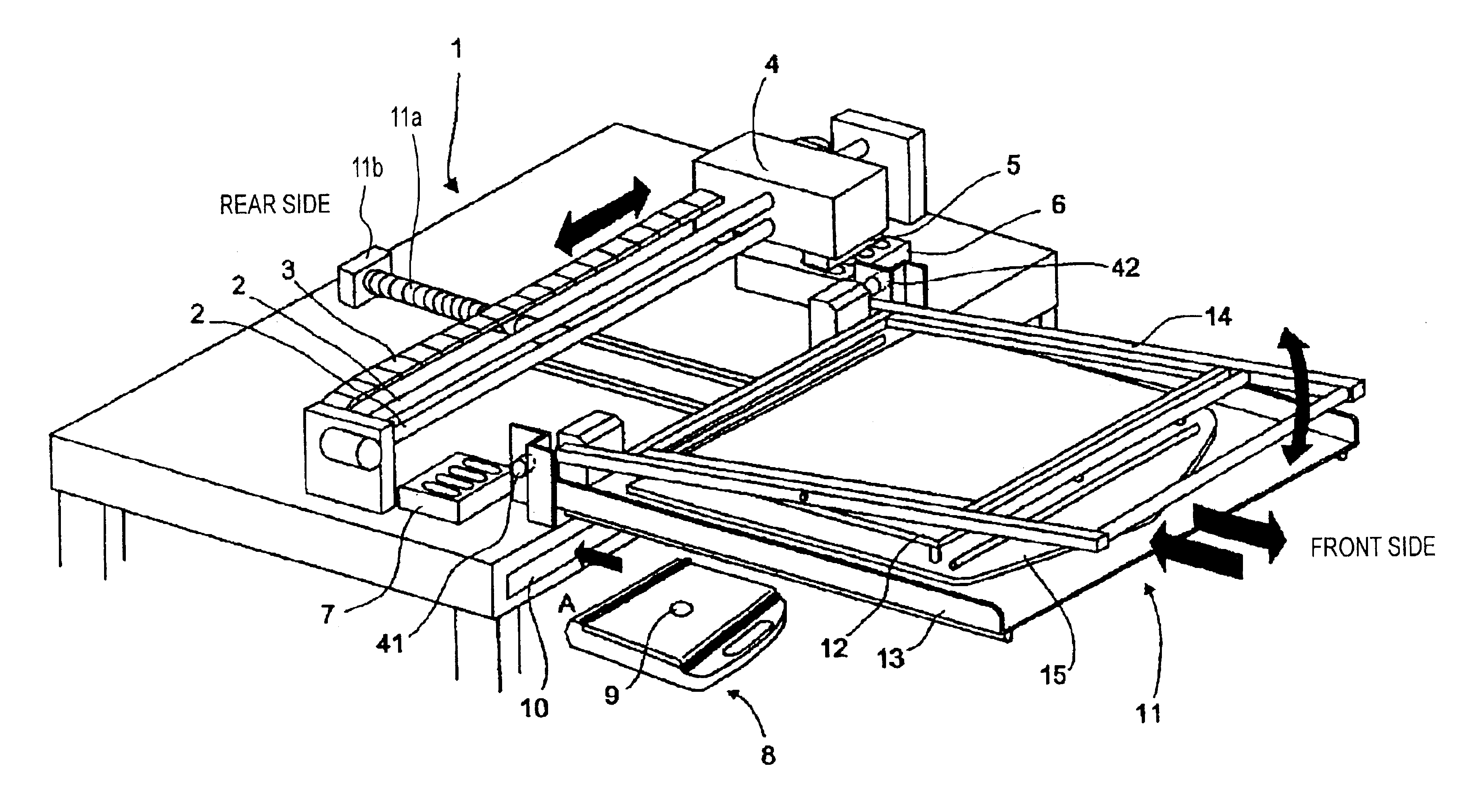
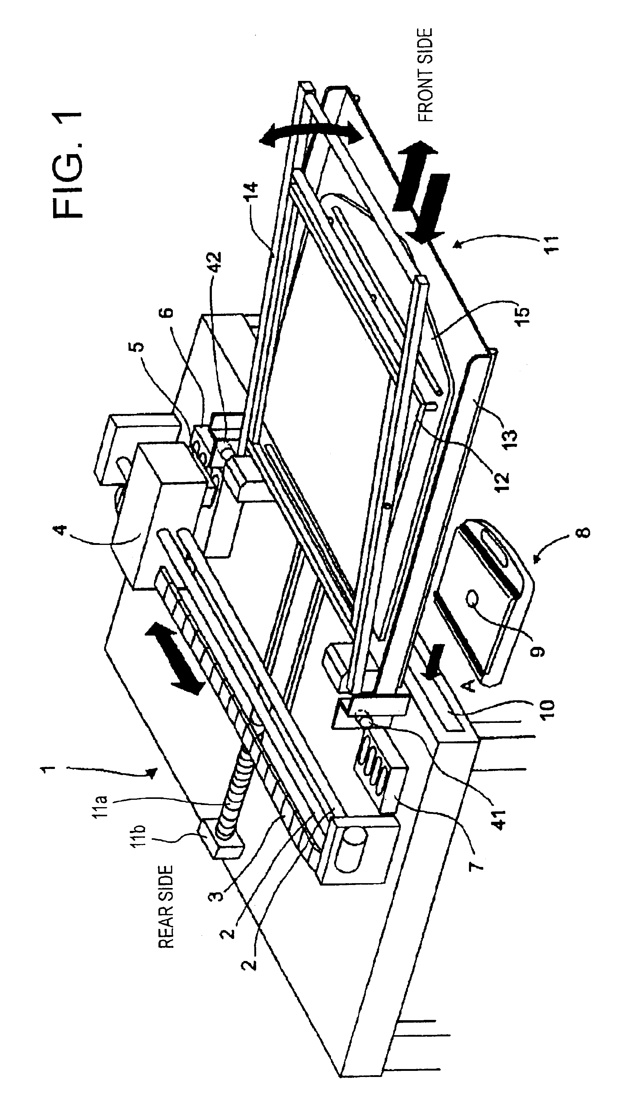
[0061]Referring to FIGS. 1-8, one preferred embodiment of the present invention will be described. Reference is first made to the perspective view of FIG. 1 schematically showing an arrangement of an ink-jet printer which is operable to perform a printing operation on a workpiece in the form of a work fabric and which is provided with a platen device constructed to hold the work fabric.

[0062]The ink-jet printer, which is indicated generally at 1, has a main body portion including: a carriage 4 carrying a printing head 5 and an ink cartridge (not shown); two guide shafts 2 supporting the carriage 4 such that the carriage 4 is slidably reciprocable in a primary scanning direction, namely, in a lateral direction of the printer 1; a drive belt 3 connected to the carriage 4 and driven by a drive source (not shown) to reciprocate the carriage 4; a cleaning unit 6 disposed at a right end of a reciprocating stroke of the carriage 4 (printing head 5) and operable to clean the printing head 5...


PUM


Abstract

A platen device for holding a workpiece in an ink-jet printer operable to perform a printing operation on a printing surface of the workpiece, said platen device being movable into a printing area in which a printing head is operated to deliver an ink onto said printing surface for thereby forming an image on said printing surface, the platen device including a platen arranged to permit the workpiece to be placed on the platen such that a printing portion of the workpiece having the printing surface is in direct contact with a surface of the platen, and a space-defining structure partially defining an accommodating space which is provided below the platen to accommodate non-printing portions of the workpiece which extend from the printing portion outwardly of the platen.

Description

[0001]The present application is based on Japanese Patent Application No. 2002-121280 filed Apr. 23, 2002, the content of which is incorporated herein by reference.BACKGROUND OF THE INVENTION[0002]1. Field of the Invention[0003]The present invention relates to a platen device of an ink-jet printer, which is arranged to hold a work fabric or other workpiece, such as a T-shirt, during a printing operation on the workpiece.[0004]2. Discussion of Related Art[0005]A silk-screen printer is conventionally used to print a desired image on a work fabric before the printed work fabric is cut and stitched into a desired garment. For instance, the printed fabric is cut and stitched into a T-shirt such that the printed image is located in the front (bosom) or the back of the T-shirt. The printing method using the silk-screen printer is suitable for a relatively large lot production of a relatively small number of kinds of garments in factories, but is not suitable for a relatively small lot prod...

Claims


Application Information

Patent Timeline
Patent Type & Authority Patents(United States)
IPC IPC(8): B41J11/02B41J3/407B41J2/01B41J11/06
CPCB41J11/06B41J3/4078
Inventor IWATSUKI, KAZUAKINAKASHIMA, KATSUNORIKIMURA, TAKESHI
Owner BROTHER KOGYO KK
Why Eureka
Try Eureka