Separable cutting mechanism for printer

a cutting mechanism and printer technology, applied in printing, typewriters, metal working devices, etc., can solve the problems of poor cutting quality, affecting the moving speed of the load, and achieving the effect of simple structure of the separable cutting mechanism

Inactive Publication Date: 2005-06-21
XINGYUN COMP
View PDF7 Cites 12 Cited by
  • Summary
  • Abstract
  • Description
  • Claims
  • Application Information

AI Technical Summary

Benefits of technology

[0007]The main objective of the present invention is to provide a simple structure of separable cutting mechanism for a printer, of which a cutting-k

Problems solved by technology

However, the cutting-knife unit 12 must drag the printing head 11 to move along on the rail during cutting, thus loading increasing will largely affect its moving speed.
In particular, if the knife's vertical moveme

Method used


Image

  • Separable cutting mechanism for printer
  • Separable cutting mechanism for printer
  • Separable cutting mechanism for printer

Examples


Embodiment Construction

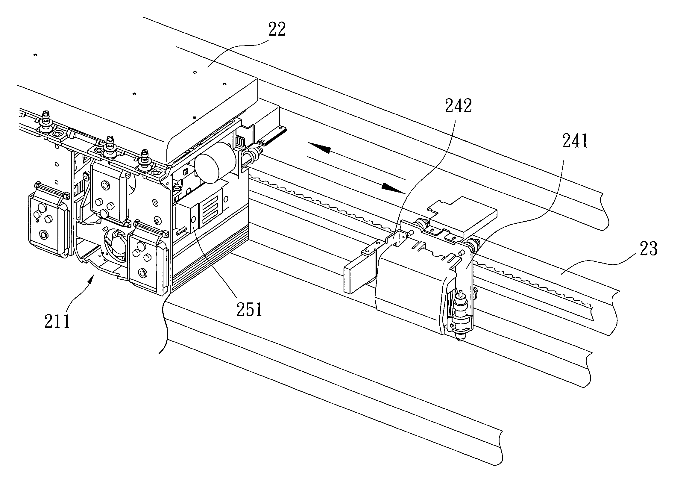
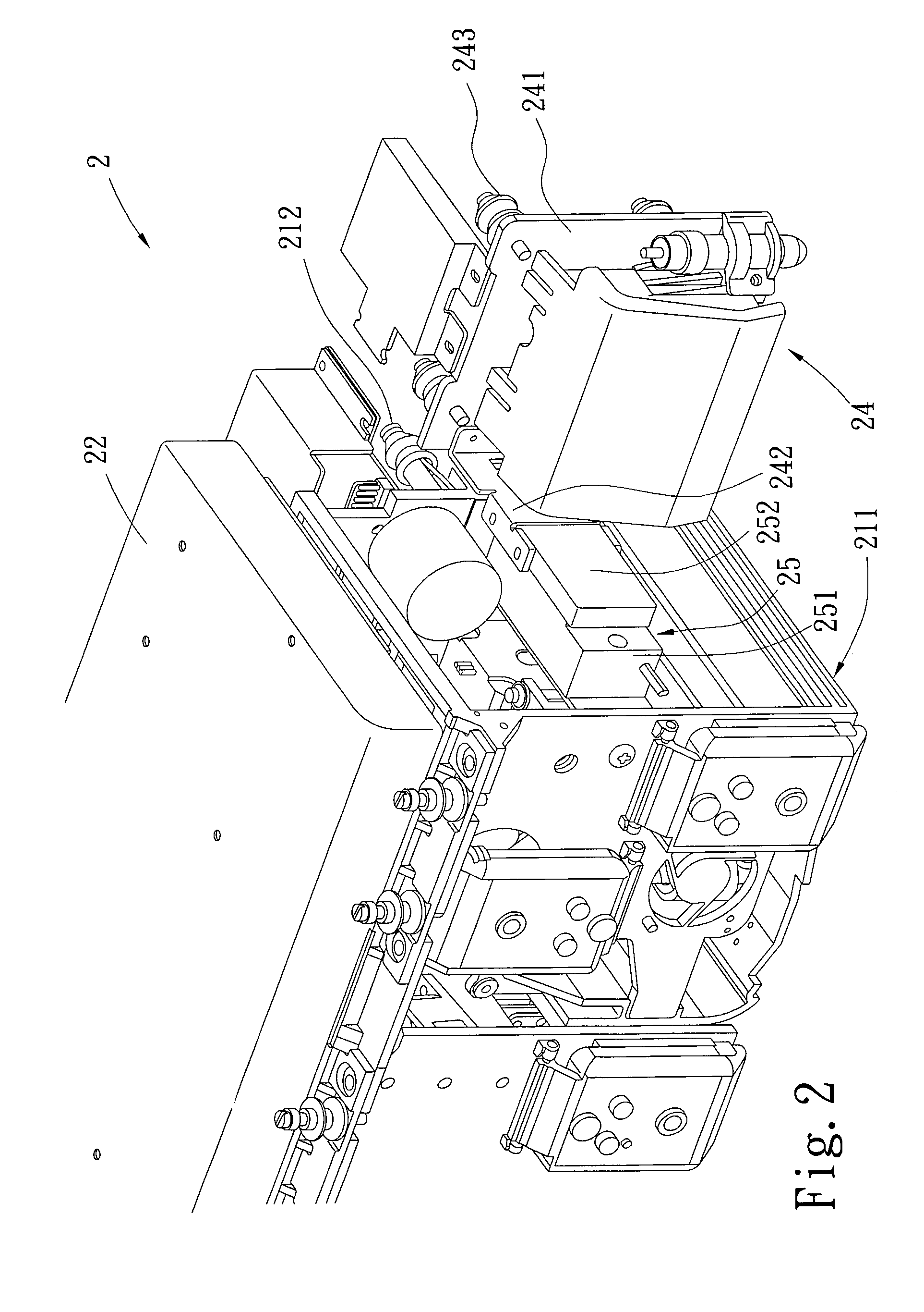
[0016]Referring to FIGS. 2 and 3 showing a separable cutting mechanism 2 for a printer of an embodiment of the present invention, it is comprised of:[0017]a printing device 21 composed of four printing heads 211 having four monochromatic cartridges 22, and provided on edges thereof with a plurality of rollers 212 to mount the printing device 21 on a rail 23 of the printer to move transversely;[0018]a cutting-knife unit 24 composed of a carrier 241 having a cutting knife thereon; the carrier 241 is provided on one edge thereof with a locking plate 242, and has a plurality of rollers 243 on one side thereof to mount the cutting-knife unit 24 on the rail 23 of the printer and being installed in juxtaposition with the printing heads 211; and[0019]an electromagnetic connector 25 provided between the printing heads 211 and the carrier 241 of the cutting-knife unit 24; the electromagnetic connector 25 is composed of a electromagnetic block 251 and a magnetically attractable metallic block ...


PUM


Abstract

A separable cutting mechanism for a printer comprises: a printing device with rollers used for mounting on a rail of the printer to move transversely; a cutting-knife unit with a carrier having rollers thereon to mount the cutting-knife unit on the rail of the printer and to be installed in juxtaposition with a plurality of printing heads; and an electromagnetic connector provided between the printing device and the carrier of the cutting-knife unit, the electromagnetic connector is provided with a magnetizing coil to generate attraction or release action when the printer is operated. Thereby, the cutting-knife unit and the printing device can be controlled to mutually attract with each other or can be separated for independent operations.

Description

BACKGROUND OF THE INVENTION[0001]1. Field of the Invention[0002]The present invention is related to a separable cutting mechanism for a printer, and especially refers to a simple cutting mechanism structure for a printer, of which a cutting-knife unit and a printing device can be mutually attracted to integrate with each other and can be separated for independent operations; it is applicable to cutting device on a printer.[0003]2. Description of the Prior Art[0004]Referring to FIG. 1, a current large advanced printer 1 is provided on a printing device with an integrated printing head 11 to print out graphics and texts, and with a cutting-knife unit 12 attached to printer 1 to cut the desired graphics and texts on paper.[0005]However, the printing head 11 and the cutting-knife unit 12 of the conventional printer 1 are designed integratedly; they must simultaneously move along on a rail during operation. The printing head 11 is designed to carry multiple ribbon cartridges 13 during co...

Claims


Application Information

Patent Timeline
IPC IPC(8): B41J11/70B26D5/02B26D5/06
CPCB26D5/02B41J11/706B26D5/06
Inventor LAI, JIN-SHENG
Owner XINGYUN COMP
Why Eureka
Try Eureka