Rotating heat exchanger

a heat exchanger and rotating technology, applied in the direction of lighting and heating apparatus, separation processes, laminated elements, etc., can solve the problems of many hours, high inefficiency, and inability to produce just a few gallons of distilled water

Inactive Publication Date: 2005-06-21
ZANAQUA TECH
View PDF34 Cites 18 Cited by
  • Summary
  • Abstract
  • Description
  • Claims
  • Application Information

AI Technical Summary

Benefits of technology

[0016]In operation, the folded heat exchanger plate is rotated about its axis, causing the rotating element to generate a rotating annular pool of liquid which is forced into the first stationary scoop tube and delivered to the open inner diameter ends of the evaporating chambers. Due to the rotation of the heat exchanger plate, this liquid is accelerated and forced outwardly. The liquid flows along the oppositely facing surfaces of the adjacent panels of the evaporating chambers, and at least a portion of the liquid is evaporated. The vapor flows through the open inner diameter ends of the evaporating chambers and enters the open central space. From the central space, the vapor flows to the compressor inlet. Any remaining, unevaporated liquid collects in the sealed outer edges of the evaporation chambers and drains back to the sum

Problems solved by technology

These boiler-type distillers require substantial amounts of electrical power to produce relatively little distilled water, and are thus highly inefficient and are used to produce only small amounts of distilled water.
They are also extremely slow, often taking many hours to produce just a few gallons of distilled water.
Accordingly, boiling-type distillers have not gained widespread acceptance or use.
The vapor is not, however, able to enter the sealed spaces.
Although it may provide some advantages, the design of the '159 evaporator presents a substantial risk of contamination of the condensate by the liquid being evaporated, and is thus not suita

Method used


Image

  • Rotating heat exchanger
  • Rotating heat exchanger
  • Rotating heat exchanger

Examples


Embodiment Construction

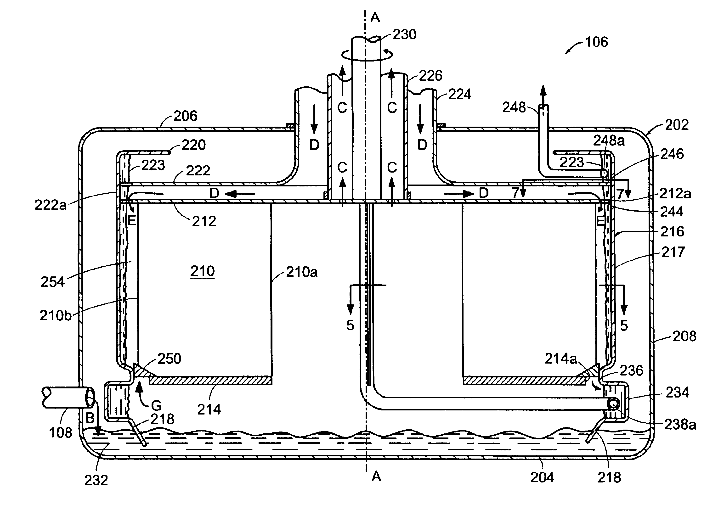
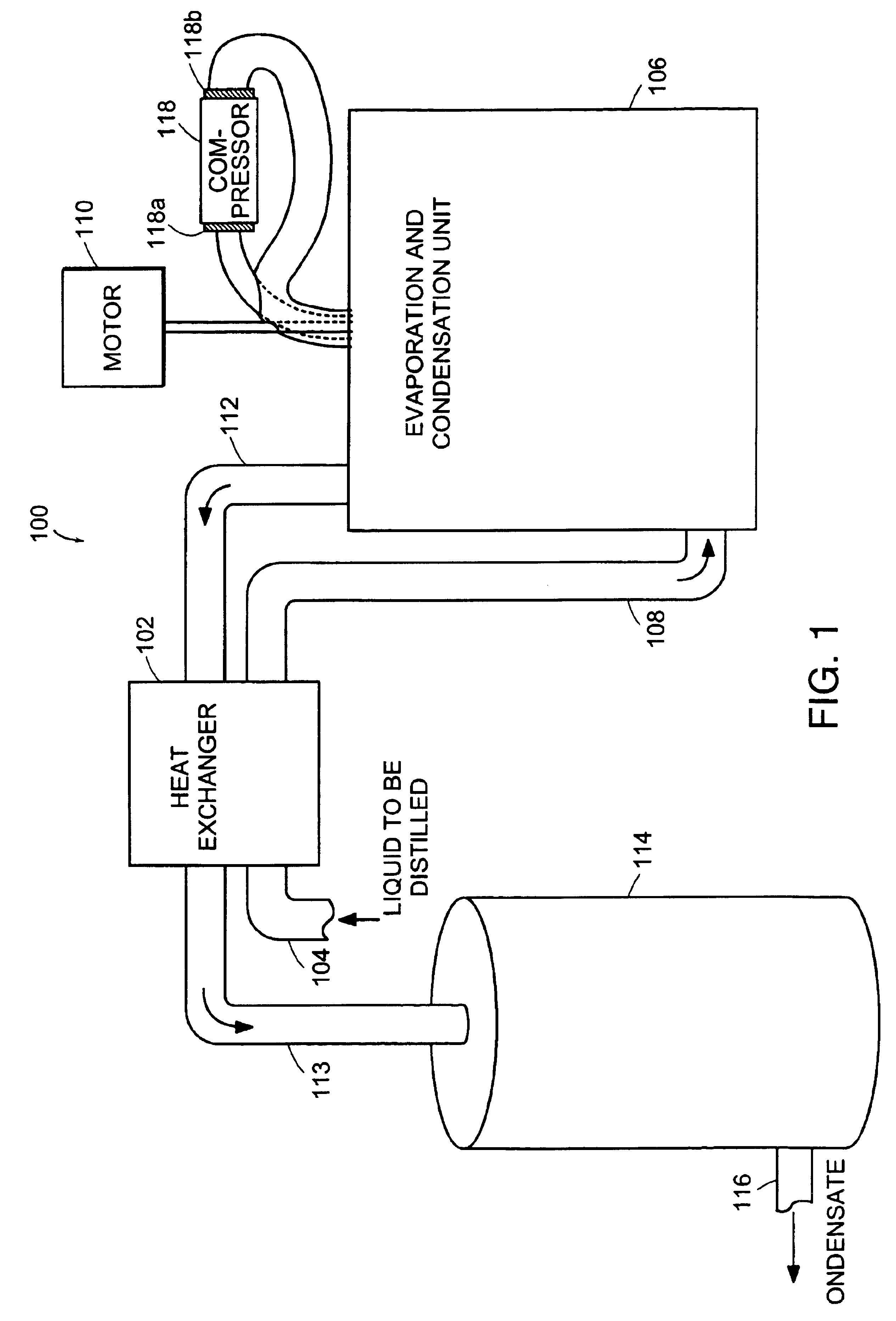
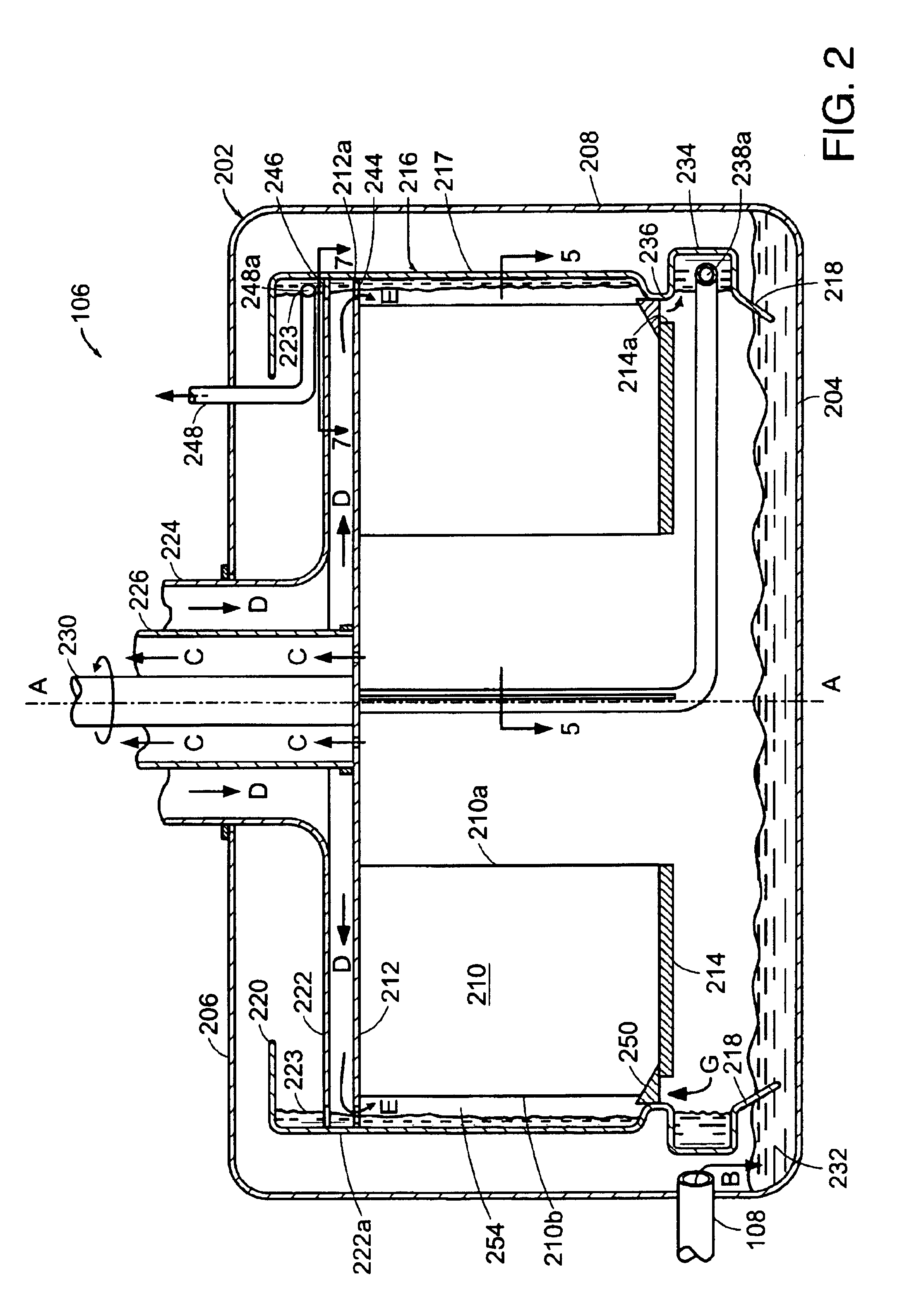
[0027]FIG. 1 is a highly schematic diagram of a vapor compression distillation system 100 in accordance with the present invention. Generally, the system 100 comprises a heat exchanger, such as counter-flow heat exchanger 102, for heating a supply of liquid to be distilled, such as non-potable water, which is received by heat exchanger 102 by first pipe 104. Heated liquid is transferred from the counter-flow heat exchanger 102 to an evaporator and condenser unit 106 by a feed line 108. Coupled to the evaporator and condenser unit 106 is a motor 110 for supplying rotary power thereto. An output line 112 transfers a condensate, such as distilled water, from the evaporation and condensation unit 106 back through the heat exchanger 102. Another line 113 transfers the condensate from the heat exchanger 102 to a holding tank 114. Condensate may be withdrawn from the holding tank 114 by pipe 116. System 100 further includes a compressor 118 having an inlet 118a and an outlet 118b. The comp...


PUM

PropertyMeasurementUnit
Diameteraaaaaaaaaa
Distanceaaaaaaaaaa

Abstract

An evaporator and condenser unit for use in distilling a liquid, such as water, includes a rotary heat exchanger plate having a plurality of folds or pleats. Adjacent panels of the folded plate define spaces between their oppositely facing surfaces, and these spaces are alternatingly configured as evaporating and condensing chambers. The evaporating chambers, moreover, are defined between adjacent panels that are joined at an outer diameter fold, while the condensing chambers are defined between adjacent panels that are joined at an inner diameter fold. The evaporating chambers are thus closed at their outer diameter ends and open at their inner diameter ends, while the condensing chambers are closed at their inner diameter ends and open at their outer diameter ends.

Description

CROSS-RELATED APPLICATIONS[0001]This application is related to the following co-pending U.S. Patent Application:[0002]U.S. patent application Ser. No. 09 / 609,881 entitled, ROTATING FLUID EVAPORATOR AND CONDENSER, filed Jul. 12, 2000, and assigned to the assignee of the present application.BACKGROUND OF THE INVENTION[0003]1. Field of the Invention[0004]This invention relates to distillation systems and, more specifically, to an improved, highly efficient, rotary evaporator and condenser for use in a vapor compression distiller.[0005]2. Background Information[0006]Distillation is a well-known method for generating potable water from otherwise unsafe water sources (such as sea water or polluted ground water). With distillation, water is heated to boiling, and the resultant vapor (i.e., steam) is collected and condensed, producing distilled water. Many contaminants that are present in the water source are left behind when the water is converted to its vapor phase. Conventional small dis...

Claims


Application Information

Patent Timeline
IPC IPC(8): B01D5/00B01D3/00B01D3/08C02F1/04F28D9/00F28D11/02F28D11/00
CPCB01D3/08B01D5/0015F28D11/02C02F1/043F28D9/0025B01D5/0024
Inventor ZEBUHR, WILLIAM H.
Owner ZANAQUA TECH
Why Eureka
Try Eureka