Adaptive and synergic fill welding method and apparatus

a welding method and synergic technology, applied in the field of material joining, can solve the problems of affecting the productivity of shipyards, the erection of ships from units, and the cost of erection welding units and super-units, and achieves the effects of improving welding quality, easy influence of a number of complex welding parameters, and low cos

Active Publication Date: 2005-06-21
EDISON WELDING INSTITUTE INC
View PDF15 Cites 42 Cited by
  • Summary
  • Abstract
  • Description
  • Claims
  • Application Information

AI Technical Summary

Benefits of technology

[0010]In its most general configuration, the present invention advances the state of the art with a variety of new capabilities and overcomes many of the shortcomings of prior methods in new and novel ways. In its most general sense, the present invention overcomes the shortcomings and limitations of the prior art in any of a number of generally effective configurations. An object of the invention is to provide a low cost adaptive and synergic fill welding method and apparatus that produces welded joints having improved weld quality and allows real-time intervention by an operator during welding to easily influence a number of complex welding parameters. The instant invention demonstrates such capabilities and overcomes many of the shortcomings of prior methods in new and novel ways.
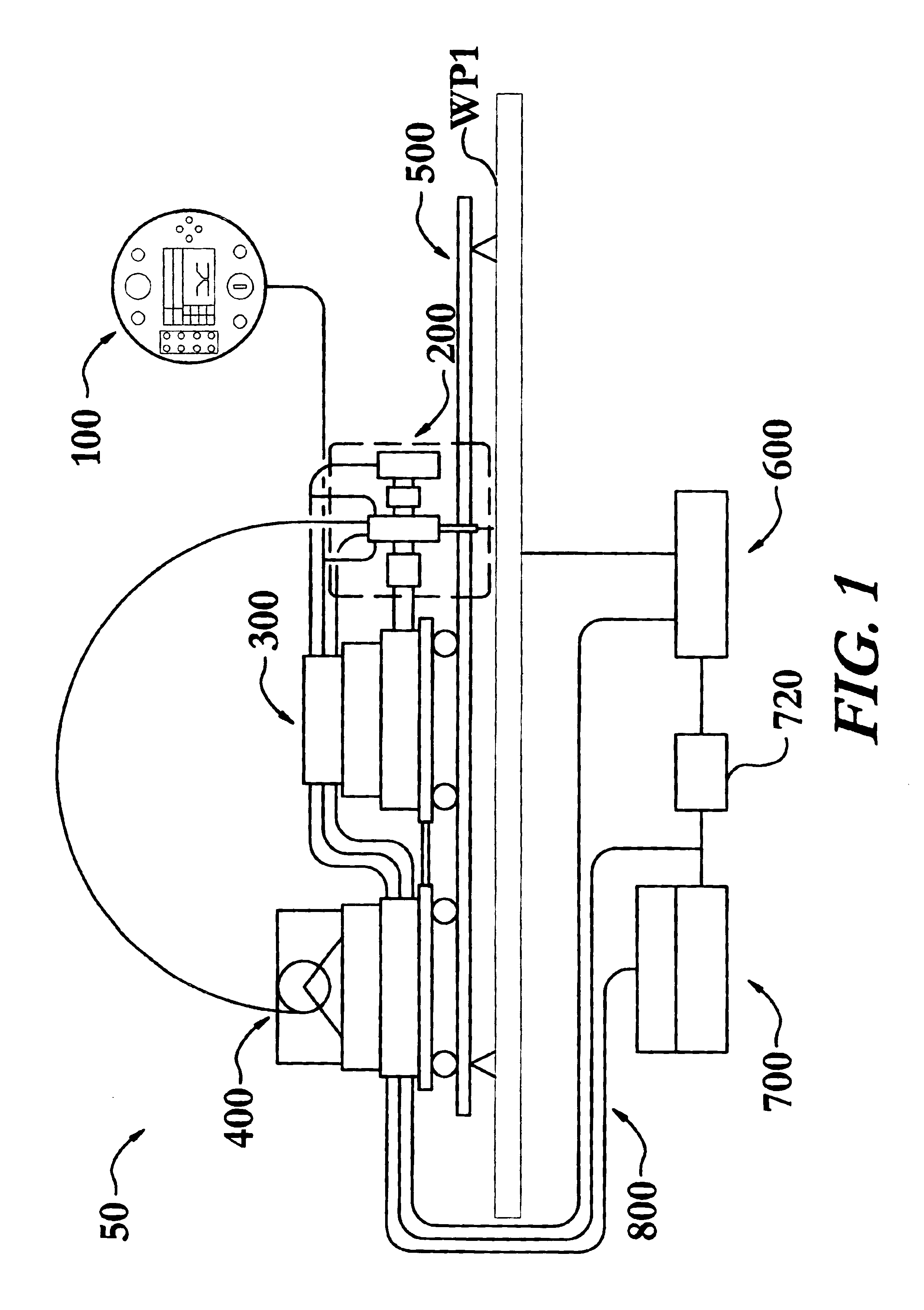
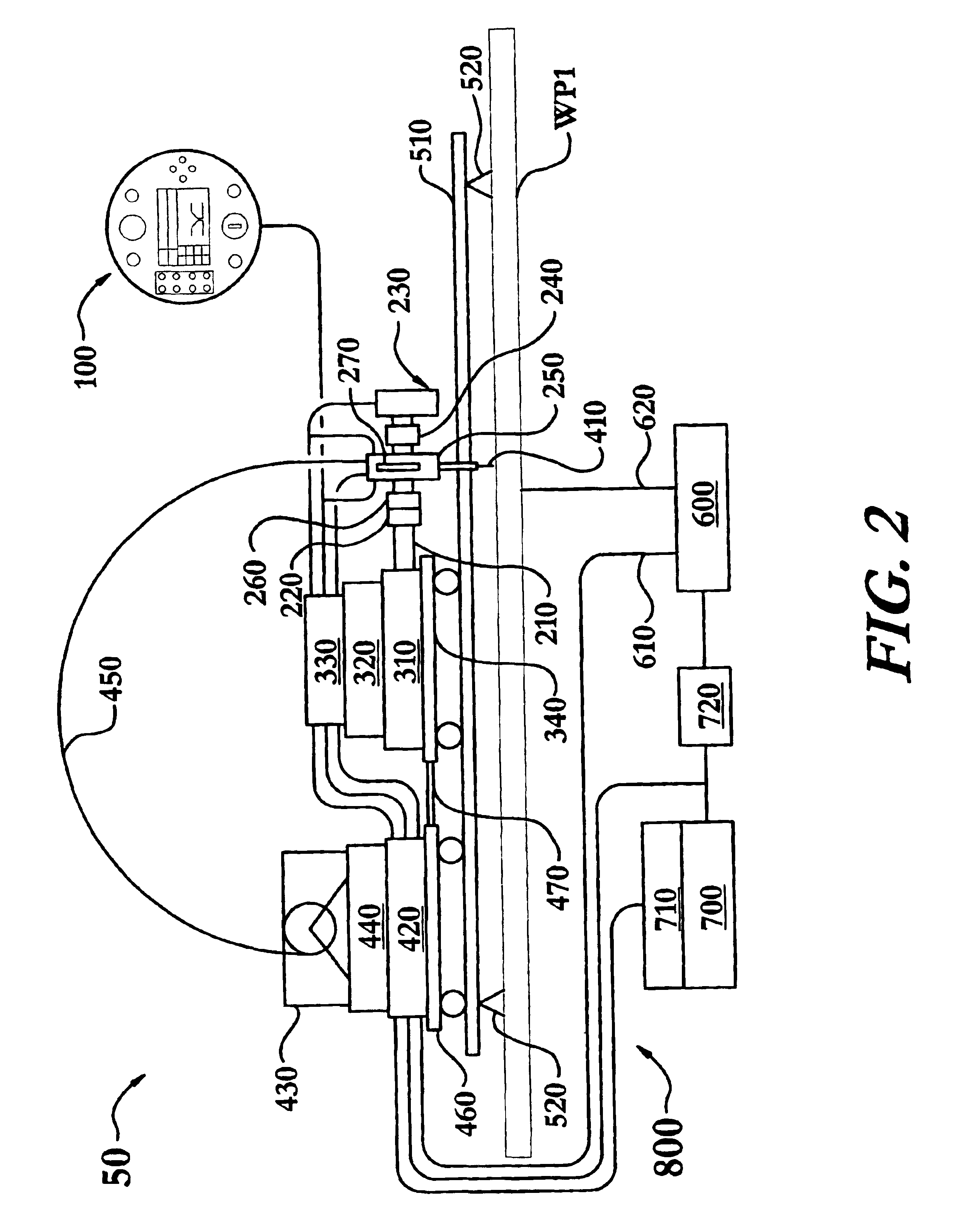
[0011]The adaptive and synergic fill welding apparatus is particularly suited for the joining of work pieces along a joint having a variable joint profile. The apparatus generally includes a means for profiling and tracking the joint, a means for welding the joint, a means for feeding a consumable electrode to the welding means, a means for controlling the power to the welding means, a means for adjusting the location of the profiling and tracking means and the welding means, a means for adjusting the rotation of the welding means, a means for moving multiple elements of the apparatus, a portable means for user input and display, a means for controlling various elements of the apparatus, and a means for communicating a plurality of input and output commands, and power among the various means of this apparatus. These means work in conjunction to provide improved fusion quality, in part by ensuring that the base metal dilution of a weld remains within a predetermined range.
[0014]In a typical configuration, the joint profile and tracking system leads the welding torch in the direction of travel by a predetermined lead distance thereby acquiring information about an upcoming section of the joint. A joint profile and tracking system position adjuster may be introduced to improve the flexibility with which the joint profile and tracking system leads the welding means, or welding torch, thereby adjusting the lead distance. Various applications, and welding speeds, may require the joint profile and tracking system to lead the welding means by varying lead distances.
[0034]While the adaptive fill mode is fully automated and does not permit user influence, the synergic fill mode permits the user to influence the welding operation during welding. The synergic fill regulation device, on the pendent, allows the user to influence the automatic welding of the apparatus. More specifically, the synergic fill regulation device permits the user to change the synergic fill number. Consequently, the size of the weld bead may be systematically set and varied with the application of different synergic fill numbers. Therefore, the concept of changing the synergic fill number and thereby changing a plurality of optimized parameters, herein referred to as synergic fill welding, not only maximizes the use of optimized welding parameters but also avoids the manual individual adjustments of a multitude of welding parameters by a user to vary the size of the weld bead having no control on the weld quality. Additionally, a manual mode provides the operator the option of controlling all of the welding parameters from the single location of the user interface pendent. This option of single point manual control provides the operator with great flexibility and convenience.
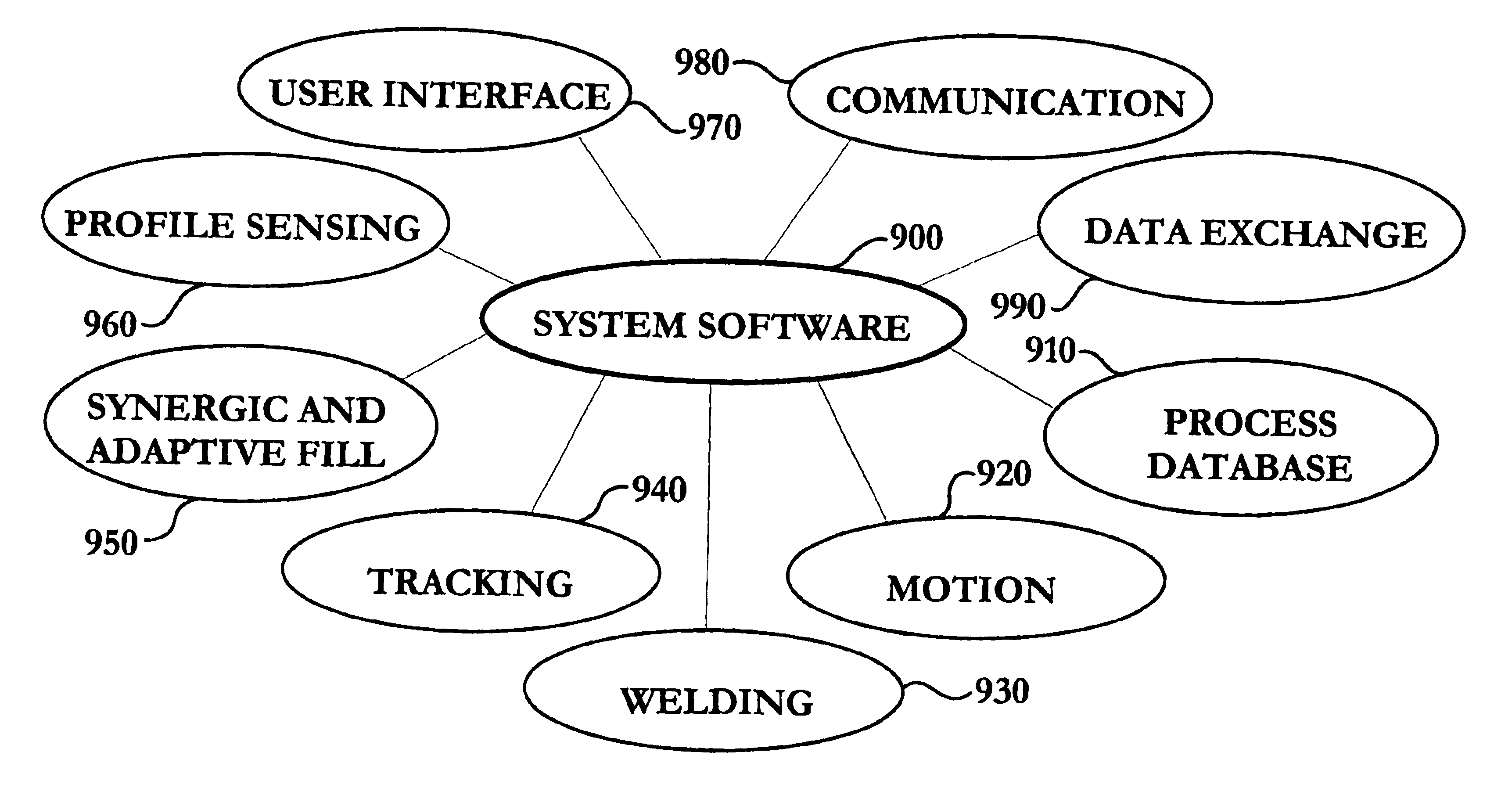
[0035]Referring back to the various software modules, the joint profile module of the instant embodiment constantly communicates with the base system software residing in the joint profile and tracking system via an RS-422 serial port to exchange data and commands. In this particular, embodiment the base software is responsible for setting up specific joint characteristics such as the joint type, base metal preparations, and certain sensor characteristics like image acquisition rate. One with skill in the art will appreciate that this module, and for that matter any module herein, may reside virtually anywhere in the apparatus, and is not limited to residing in the joint profile and tracking system. This module accesses the joint profile and tracking system to gather and process information about the joint geometry, derive tracking data, calculate the area and area change of an unfilled joint groove, turns the joint profile and tracking system on and off and accepts position data of the welding torch. The user interface module of the instant embodiment may be embedded to the user interface pendent for interacting with the user via any of the user interface devices. Further, the module may translate and dispatch commands issued by the user via an RS-422 serial port after analysis of the status of the various user interface devices of the pendent. The communication module of the instant embodiment is implemented between the system controller and the pendent, and between the system controller and the joint profile and tracking system controller, via two RS-422 serial ports in order to achieve fast and reliable data exchange. The communication of the system software with the pendent is activated by channel build-up software, which is developed using multithreads approach to meet the requirement of random talking.

Problems solved by technology

However, to date, very few automated welding systems have effectively dealt with weld joints having continuously variable characteristics.
For example, in the shipbuilding industry, a major limitation on the productivity of a shipyard is the erection of the ship from units.
The cost of erection welding the units and super-units is often more than five times the cost of production welding the panels due in part to the extensive labor required for fit-up of the units.
Fit-up issues most commonly arise due to distortions and the accumulation of fabrication tolerances causing variable gaps and mismatch along the weld seams.
Currently, systems are limited in the quality of the welds produced and in the amount of adverse fit-up conditions that may be overcome in trying to produce a uniform groove fill.
More advanced robotic tractors have been developed to track weld seams and perform some degree of adaptive welding, yet they are generally too costly and heavy to employ in shipyard fabrication and provide little if any control on the quality of the welds produced.
For instance, laser-guided welding robots have been developed for erection welding, but such systems typically cost over $150,000 and require significant operator training and programming.
Such systems are only justified on the most critical weldments, particularly where 100% UT volumetric inspection is required.
Prior adaptive welding methods have lacked the ability to ensure weld quality in part because they generally focus on only varying one of the wire feed speed, the voltage, or the travel speed of the welding tractor.
Weld quality cannot be assured by varying only one of these variables.
Additionally, prior art systems have lacked the ability to allow a user to easily change numerous complex welding parameters at the same time, with a single input to influence the weld bead size, while maintaining the weld quality during the welding process.
While some of the prior art devices attempted to improve the state of the art, none have achieved the benefits of the present invention.
Additionally, the prior art has generally not provided the level of quality control available from the present invention.

Method used


Image

  • Adaptive and synergic fill welding method and apparatus
  • Adaptive and synergic fill welding method and apparatus
  • Adaptive and synergic fill welding method and apparatus

Examples


Embodiment Construction

[0051]The adaptive and synergic fill welding apparatus of the present invention enables a significant advance in the state of the art. The preferred embodiments of the apparatus accomplish this by new and novel arrangements of elements and methods that are configured in unique and novel ways and which demonstrate previously unavailable but preferred and desirable capabilities. In particular, the apparatus is a low-cost, easy to use, device that provides a significant advance in the quality and control of adaptive and synergic welding systems. The detailed description set forth below in connection with the drawings is intended merely as a description of the presently preferred embodiments of the invention, and is not intended to represent the only form in which the present invention may be constructed or utilized. The description sets forth the designs, functions, means, and methods of implementing the invention in connection with the illustrated embodiments. It is to be understood, ...


PUM

PropertyMeasurementUnit
voltageaaaaaaaaaa
welding voltageaaaaaaaaaa
sizeaaaaaaaaaa

Abstract

An adaptive and synergic fill welding method and apparatus enables automatic, or adaptive fill, and user directed, or synergic fill, modes to provide improved fusion quality, by ensuring that base metal dilution of a weld remains within a predetermined range. The apparatus includes a means for profiling and tracking a joint, and multi-part adjustable welding means. In adaptive fill mode the method automatically varies a plurality of welding parameters in response to measured variations such as joint width between work pieces. In synergic fill mode, the method enables a user to vary multiple welding parameters in response to joint variations by adjusting a single variable, a synergic fill number, which may be controlled by means of a user interface pendent. The multiple welding parameters may include predetermined wire feed speed, torch travel speed, welding voltage and current, torch oscillation width, dwell time, and a plurality of bead size parameters.

Description

STATEMENT REGARDING FEDERALLY SPONSORED RESEARCH OR DEVELOPMENT[0001]This invention was made with government support under Contract No. N00140-96-C-0188 awarded by the Office of Naval Research, United States Department of the Navy. The government has certain rights in the invention.TECHNICAL FIELD[0002]The present invention relates to the field of material joining; particularly, to an adaptive and synergic fill welding method and apparatus that produces high quality welds having a predetermined base metal dilution.BACKGROUND OF THE INVENTION[0003]Numerous industries have long sought to reduce the amount of labor necessary to join various work pieces by welding, while increasing the quality of the joints. In fact, automated welding systems have greatly improved weld quality while reducing costs in many industries. However, to date, very few automated welding systems have effectively dealt with weld joints having continuously variable characteristics.[0004]The effects of weld joints w...

Claims


Application Information

Patent Timeline
Patent Type & Authority Patents(United States)
IPC IPC(8): B23K9/127
CPCB23K9/1274
Inventor ZHENG, BINGHARWIG, DENNIS DUANEHUANG, TA-CHIEHREICHERT, CONSTANCE THERESA
Owner EDISON WELDING INSTITUTE INC
Why Eureka
Try Eureka