Torque sensor and robot apparatus

a technology of torque sensor and robot, which is applied in the direction of force/torque/work measurement apparatus, instruments, manufacturing tools, etc., can solve the problems of increasing the size of the torque sensor, difficult to completely cancel, and difficult to apply the above-mentioned design to an application where a reduction in size and weight is needed, so as to achieve the effect of being easier to influen

Active Publication Date: 2012-10-23
SONY CORP
View PDF24 Cites 17 Cited by
  • Summary
  • Abstract
  • Description
  • Claims
  • Application Information

AI Technical Summary

Benefits of technology

[0006]However, it is difficult to completely cancel, through the bearing, vibrations of the rotation portion in the radial direction. Therefore, outputs of the torque sensor are easy to be significantly varied even with minute vibrations generating in the rotational portion. By the way, the torque sensor is often fastened with screws to the rotational portion, and the strain generated on the strain portion is also influenced by the fastening forces of the screws. The fastening forces of the screws are varied due to the magnitude of loads and the vibrations of the rotational portion, which makes the torque sensor easier to be influenced by the loads and the vibrations.
[0007]In order to overcome the above-mentioned problems, it may be conceivable that a design that portions fastened with the screws are provided geometrically away from the strain body as much as possible is employed. However, the above-mentioned design leads to an increase of the size of the torque sensor, and hence it is difficult to apply the above-mentioned design to an application where a reduction in size and weight is demanded, for example, a mobile robot. Further, in order to eliminate vibration components, a design with tight fittings and dimensional tolerance with less loosening is basically employed. As a result, a stress among mechanical components is increased, and hence the torque sensor portion becomes easier to influenced by compression and pulling forces by other components and fastening forces of the other components.

Problems solved by technology

However, it is difficult to completely cancel, through the bearing, vibrations of the rotation portion in the radial direction.
However, the above-mentioned design leads to an increase of the size of the torque sensor, and hence it is difficult to apply the above-mentioned design to an application where a reduction in size and weight is demanded, for example, a mobile robot.

Method used


Image

  • Torque sensor and robot apparatus
  • Torque sensor and robot apparatus
  • Torque sensor and robot apparatus

Examples


first embodiment

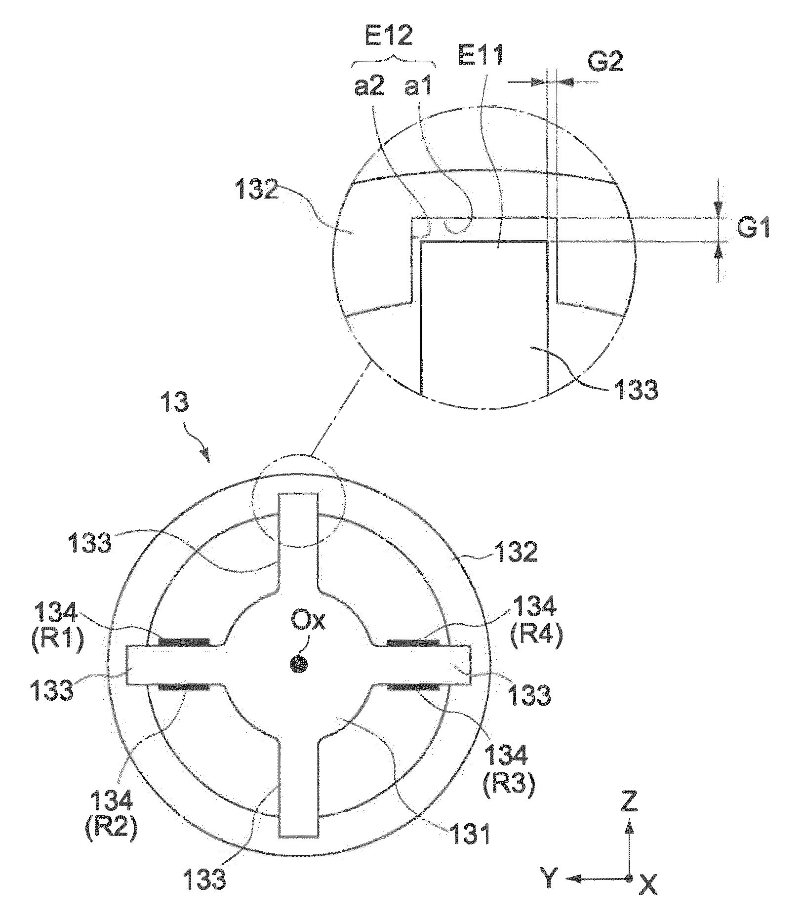
[0049]In the first embodiment, the inner ring 131 and the outer ring 132 are formed of a pair of concentric annular bodies. The pair of concentric annular bodies are arranged so as to be opposed to each other in a direction perpendicular to the X-axis direction, that is, a direction parallel to the YZ plane, and have diameters different from each other. The strain bodies 133 are integrally formed with the inner ring 131. The inner ring 131 is supported through the strain bodies 133 to the outer ring 132. The materials of the inner ring 131, the outer ring 132, and the strain bodies 133 are not particularly limited, and various structural materials made of an iron and steel material and a non-ferrous metal material can be used for the materials. For example, there may be used a material relatively easy to be elastically deformed when receives the rotational torque generated through the speed reducer 12.

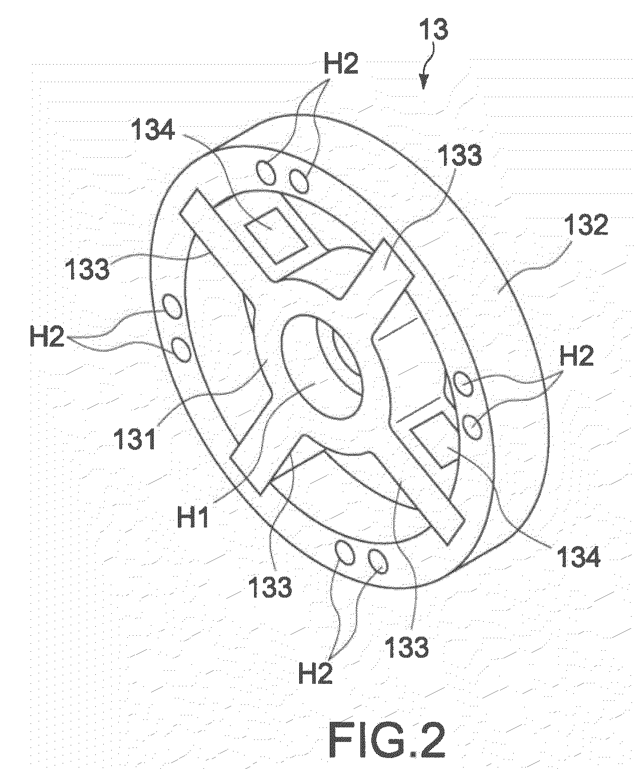
[0050]In the center portion of the inner ring 131, there is formed a screw hole H1...

second embodiment

[0075]Next, the present invention will be described.

[0076]FIG. 8 is a front view of a torque sensor according to the second embodiment. The torque sensor 23 of the second embodiment includes an inner ring 231 (first rotating body), an outer ring 232 (second rotating body), and strain bodies 233. Similarly to the first embodiment, the inner ring 231 and the outer ring 232 are formed of a pair of concentric annular bodies. The pair of concentric annular bodies are arranged so as to be opposed to each other in a direction perpendicular to the X-axis direction, that is, a direction parallel to the YZ plane, and have diameters different from each other.

[0077]The inner ring 231 includes an input shaft to which an output torque of the speed reducer is input, and the outer ring 232 includes an output shaft (Ox) for rotating an output member. The strain bodies 233 are supported between the inner ring 231 and the outer ring 232, and transmit the output torque of the speed reducer from the inn...

third embodiment

[0083]In the third embodiment, the first rotating body 331 and the second rotating body 332 are formed of a pair of annular bodies arranged so as to be opposed to each other in the X-axis direction. The strain body 333 has a cylindrical shape (cylindrical portion) extending between the first rotating body 331 and the second rotating body 332 in the X-axis direction. Both end portions of the strain body 333 are engaged through an engaging structure 33a and an engaging structure 33b, which are schematically shown in hatching in FIG. 9, to the first rotating body 331 and the second rotating body 332, respectively. The materials of the first rotating body 331, the second rotating body 332, and the strain body 333 are not particularly limited, and various structural materials made of an iron and steel material and a non-ferrous metal material can be used for the material. For example, there may be used a material relatively easy to be elastically deformed when receives the rotational tor...


PUM

PropertyMeasurementUnit
sizeaaaaaaaaaa
rotational torqueaaaaaaaaaa
diametersaaaaaaaaaa

Abstract

Provided is a torque sensor including a first rotating body, a second rotating body, a strain body, and a detection element. The first rotating body is rotatable around an input shaft. The second rotating body is rotatable around an output shaft. The strain body includes a first engaging portion. The first engaging portion is separated from at least one of the rotating bodies in a first direction parallel to the input shaft, a second direction perpendicular to the first direction, and a third direction around the input shaft and is capable of engaging to the at least one of the rotating bodies in the third direction. The strain body transmits a rotational torque to the third direction between the first rotating body and the second rotating body. The detection element is provided to the strain body to measure a strain of the strain body due to the rotational torque.

Description

BACKGROUND OF THE INVENTION[0001]1. Field of the Invention[0002]The present invention relates to a torque sensor configured to detect a rotational torque transmitted from an input shaft to an output shaft, and a robot apparatus including the same.[0003]2. Description of the Related Art[0004]In recent years, torque sensors have been applied, for example, to an actuator control apparatus employing a force control system and to a driving system such as a haptic device for providing an operator with a sense of force and a tactile sense in addition to visual information and audio information. Here, the force control means a control method for directly receiving a target value of a force to be applied to a work object and realizing the force indicated by the target force. Further, as an output torque is detected and fed back with higher accuracy, more flexible interaction services can be achieved through force orders. Further, the haptic device is a device configured to provide in a reali...

Claims


Application Information

Patent Timeline
Patent Type & Authority Patents(United States)
IPC IPC(8): G01L1/22G01L3/00
CPCB25J13/085G01L3/1457
Inventor NAGASAKA, KENICHIROKAWANAMI, YASUNORI
Owner SONY CORP
Why Eureka
Try Eureka