Driving LED's

Inactive Publication Date: 2012-06-21
KONINKLIJKE PHILIPS ELECTRONICS NV
View PDF3 Cites 16 Cited by
  • Summary
  • Abstract
  • Description
  • Claims
  • Application Information

AI Technical Summary

Benefits of technology

[0005]It is an object of the invention to provide a drive circuit for driving a plurality of LED strings to coun

Problems solved by technology

This approach has the drawback that a large number of coupled inductors is

Method used


Image

  • Driving LED's
  • Driving LED's
  • Driving LED's

Examples


Example

[0026]It should be noted that items which have the same reference numbers in different Figures, have the same structural features and the same functions, or are the same signals. Where the function and / or structure of such an item has been explained, there is no necessity for repeated explanation thereof in the detailed description.

DETAILED DESCRIPTION

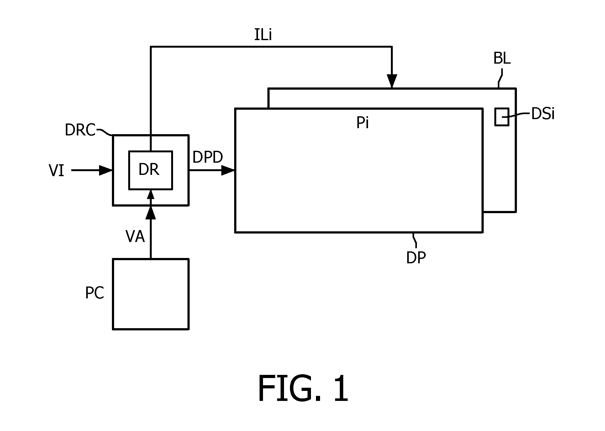
[0027]FIG. 1 schematically shows a high level block diagram of a display apparatus. The display apparatus comprises a backlight unit BL, a display panel DP, a drive circuit DRC and a power converter PC.

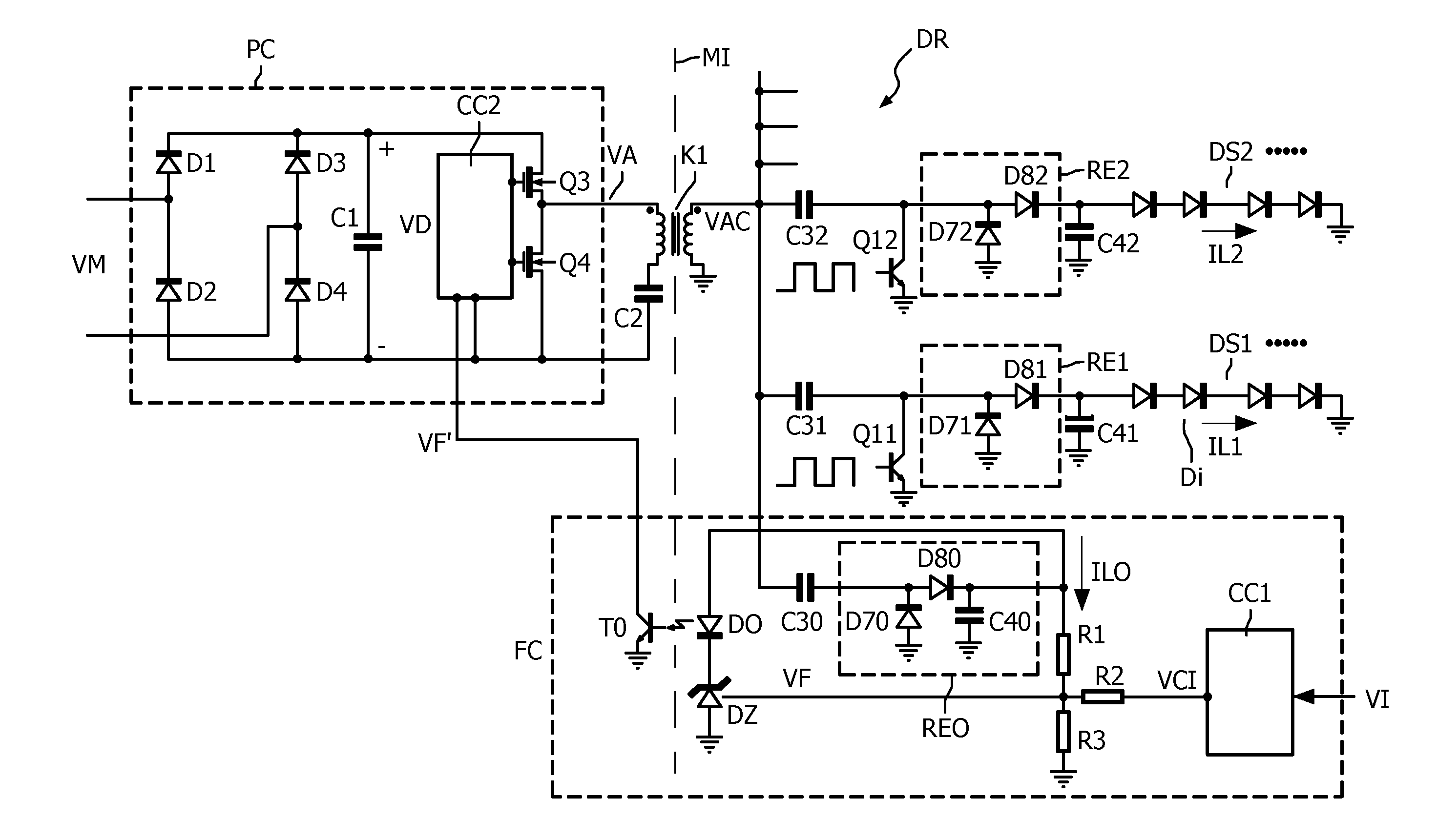
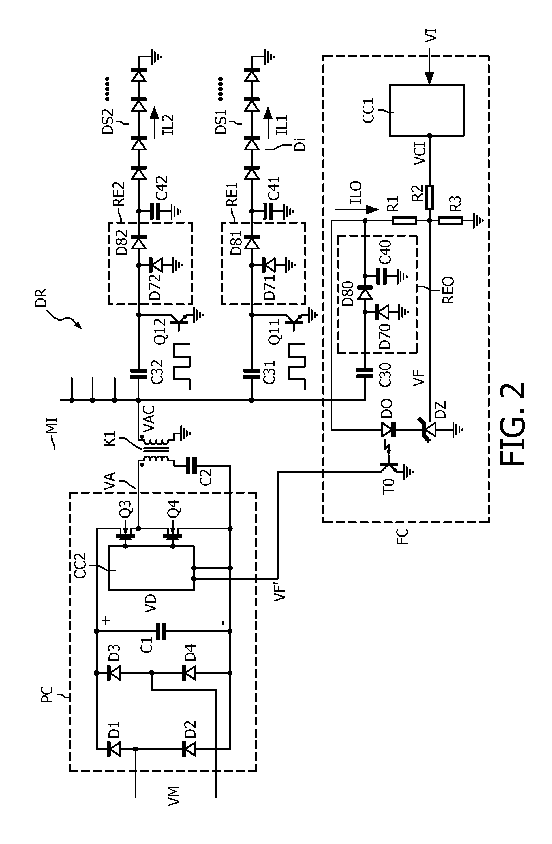
[0028]The backlight unit BL comprises the strings of LED's. Only one string DSi of the strings of LED's is shown. The display panel DP comprises pixels Pi (not explicitly shown) which usually are arranged in a matrix of rows and columns. The power converter PC supplies a power supply voltage to the drive circuit DR. The power converter PC may be fed by the mains or by a battery. The processing circuit DRC generates drive signals DPD to c...


PUM


Abstract

A drive circuit (DR) drives a plurality of LED strings (DS1, DS2; DS10) each comprising at least one LED (Di). The drive circuit comprises a resonance inductor (K1), and a plurality of branches which each comprise a series arrangement of a resonance capacitor (C31, C32; C34, C35) and an associated one of the plurality of LED strings (DS1, DS2; DS10). The resonance capacitor (C31, C32; C34, C35) is arranged between the resonance inductor (K1) and its associated one of the plurality of LED strings (DS1, DS2; DS10) to receive a resonance voltage (VAC) from the resonance inductor (K1). A level and frequency of the resonance voltage (VAC) and an impedance of the resonance capacitor (C31, C32; C34, C35) are selected to obtain a current source supplying a LED current (IL1 IL2; IL10) through the associated one of the plurality of LED strings (DS1, DS2; DS10) which is substantially independent on a tolerance on forward voltages of LED's of the associated one of the plurality of LED strings (DS1, DS2; DS10).

Description

FIELD OF THE INVENTION[0001]The invention relates to a drive circuit for driving a plurality of LED strings each comprising at least one LED (Light Emitting Diode). The invention further relates to a LED circuit comprising the drive circuit and the LED strings, to a backlight unit for a display apparatus, and to a display apparatus comprising a display panel and the backlight unit.BACKGROUND OF THE INVENTION[0002]WO 2007 / 060129 A2 discloses a driving arrangement for feeding a current generated by a high frequency generator to a plurality of LED cells each including at least one LED. The driving arrangement includes a respective plurality of LED channels arranged in a parallel configuration and one or more coupled inductors coupling in pairs the plurality of LED channels. The coupled inductors in the channels perform current equalization of LED currents even in the presence of very different forward voltages in the channels.[0003]When applying a high frequency voltage source to a pai...

Claims


Application Information

Patent Timeline
IPC IPC(8): G09G3/32H05B37/00H05B44/00
CPCY02B20/347H05B33/0815Y02B20/30H05B45/3725H05B45/10
Inventor DECRAEMER, ALAINDE MEERSMAN, ERIK
Owner KONINKLIJKE PHILIPS ELECTRONICS NV
Why Eureka
Try Eureka