Electronic pressure sensitive transducer apparatus and method for manufacturing same

a technology of electronic pressure sensitive transducer and transducer, which is applied in the direction of resistors with plural resistive elements, inspection/indentification of circuits, instruments, etc., can solve the problems of increasing the cost of pressure sensitive transducer systems and increasing the likelihood of system failure, so as to reduce the cost and complexity of electronic pressure sensitive transducers

Inactive Publication Date: 2005-06-21
INTERLINK ELECTRONICS
View PDF49 Cites 88 Cited by
  • Summary
  • Abstract
  • Description
  • Claims
  • Application Information

AI Technical Summary

Benefits of technology

[0008]The present invention decreases the cost and complexity of an electronic pressure sensitive transducer by constructing such a transducer directly on a printed circuit board containing support electronics.
[0011]In another embodiment of the present invention, a pedestal is formed on the printed circuit board substantially around the contact area. The pedestal receives the adhesive spacer for attaching the flexible substrate. The pedestal increases the space between resistive layers on the substrate and conductive traces on the printed circuit board. The pedestal may be formed by coating traces on the printed circuit board with a non-conductive material such as soldermask.

Problems solved by technology

While either method is effective, both have unnecessary manufacturing steps and require unnecessary components, thus increasing the cost of a pressure sensitive transducer system as well as increasing the likelihood of system failure.

Method used


Image

  • Electronic pressure sensitive transducer apparatus and method for manufacturing same
  • Electronic pressure sensitive transducer apparatus and method for manufacturing same
  • Electronic pressure sensitive transducer apparatus and method for manufacturing same

Examples


Embodiment Construction

)

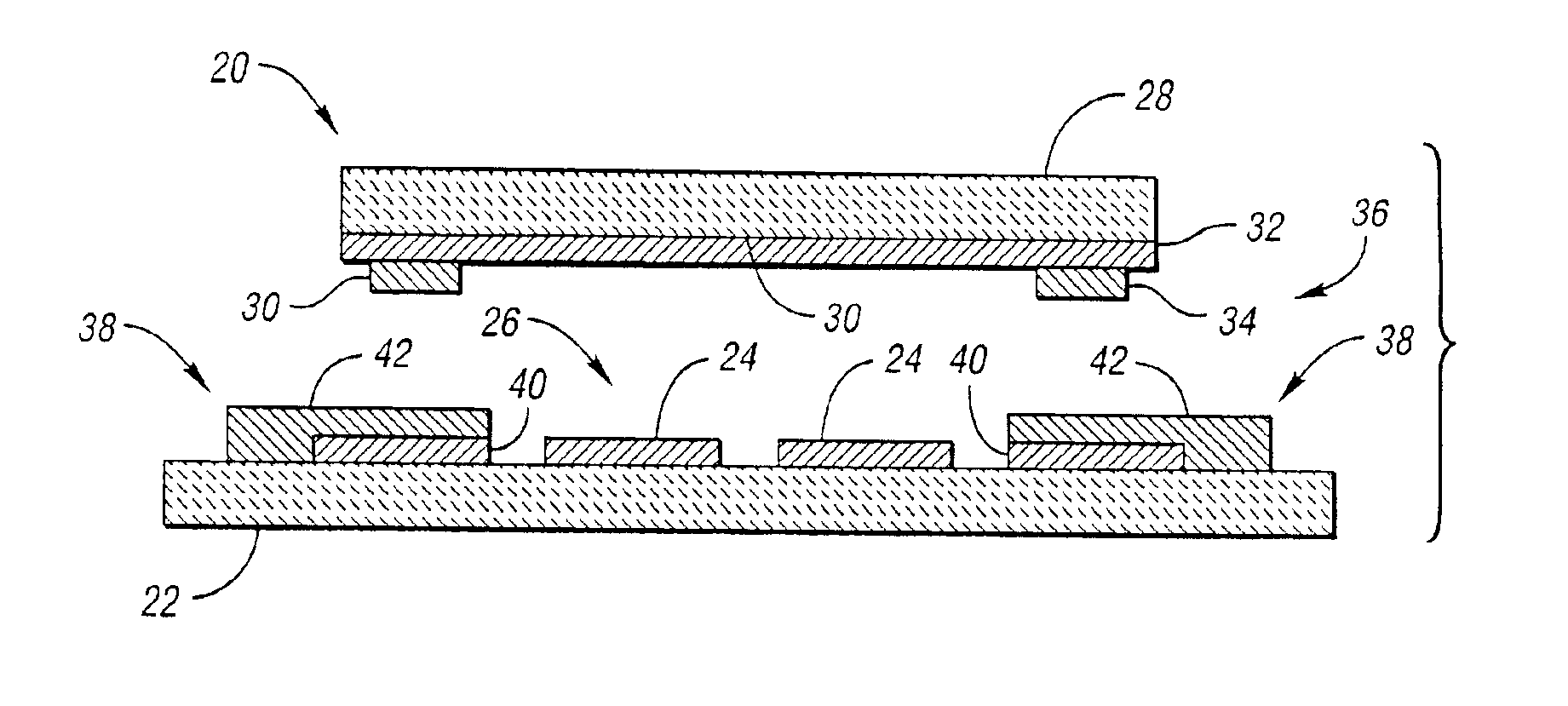
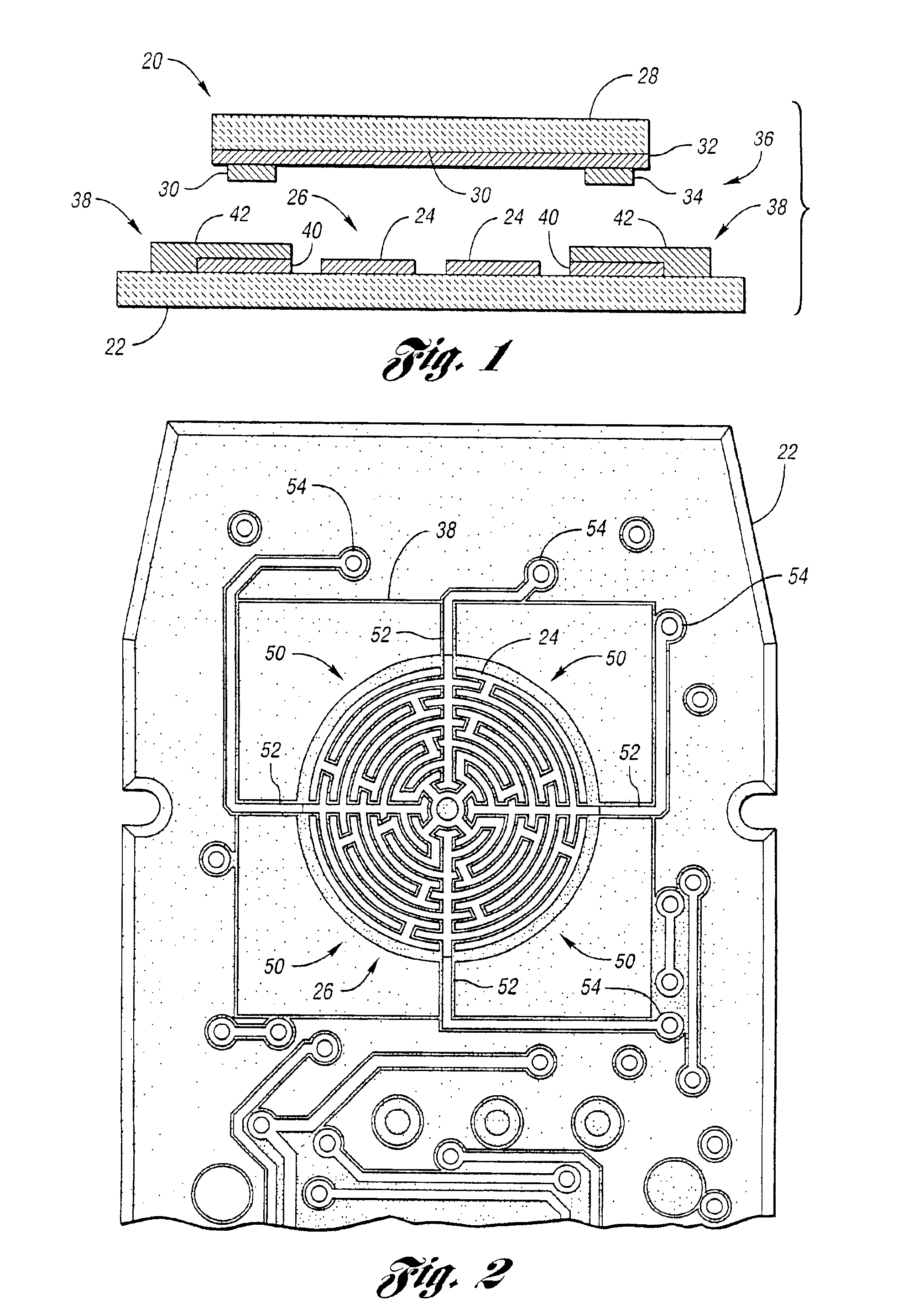
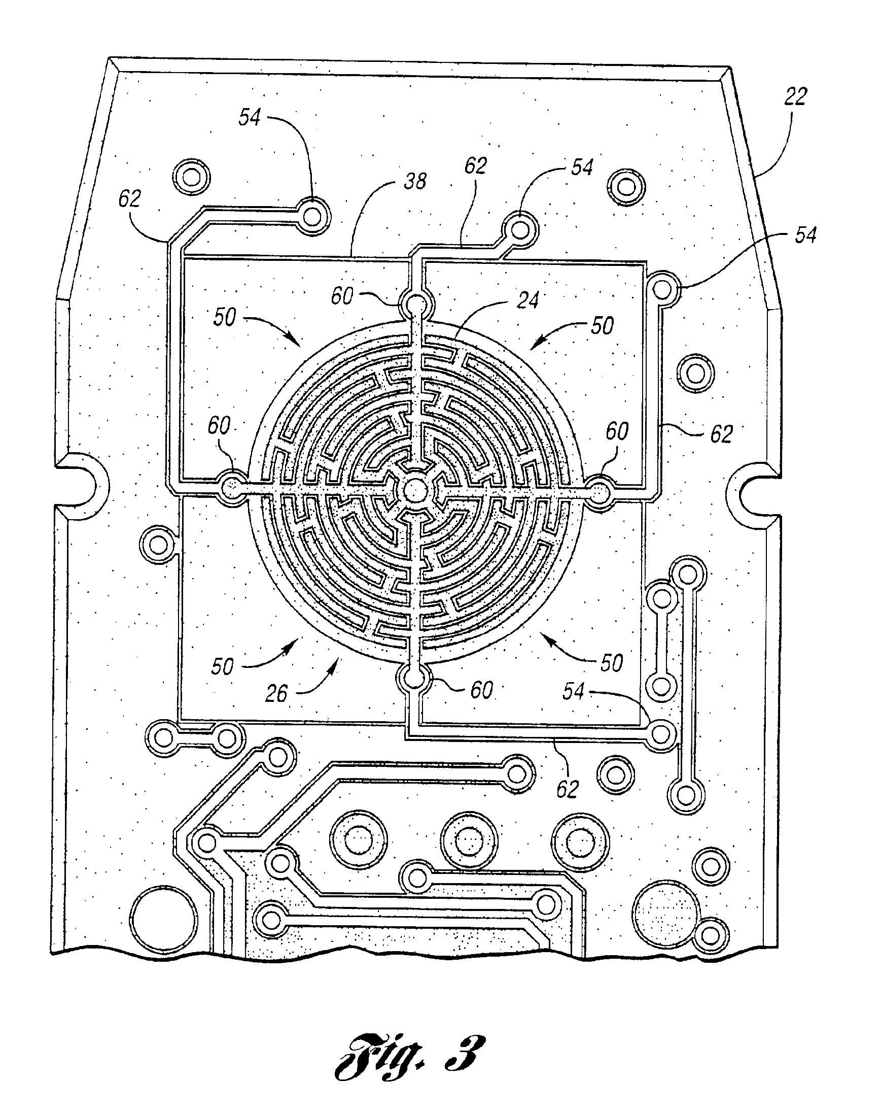
[0026]Referring to FIG. 1, an exploded cross-sectional view illustrating a conceptualized pressure sensitive transducer according to an embodiment of the present invention is shown. An electronic pressure sensitive transducer, shown generally by 20, produces an electrical signal indicative of applied pressure. Pressure transducer 20 includes printed circuit board 22 accepting a plurality of electronic elements, not shown for clarity, for processing the transducer electrical signal. Conductive traces 24 are formed on printed circuit board 22 to define contact area 26. Flexible substrate 28 has inner surface 30 which faces contact area 26 when pressure transducer 20 is assembled. At least one resistive layer 32 is deposited on inner surface 30. Adhesive spacer 34 substantially surrounds contact area 26. Adhesive spacer 34 attaches flexible substrate 28 to printed circuit board 22. When assembled, resistive layer 32 contacts at least two traces 24 in response to pressure applied to fl...


PUM

PropertyMeasurementUnit
thicknessesaaaaaaaaaa
pressureaaaaaaaaaa

Abstract

The cost and complexity of an electronic pressure sensitive transducer are decreased by constructing such a transducer directly on a printed circuit board containing support electronics. Conductive traces are formed on the printed circuit board to define a contact area. A flexible substrate having an inner surface is positioned over the contact area. An adhesive spacer, substantially surrounding the contact area, attaches the flexible substrate to the printed circuit board. At least one resistive layer is deposited on the flexible substrate inner surface. In use, the resistive layer contacts at least two conductive traces in response to pressure applied to the flexible substrate to produce an electrical signal indicative of applied pressure.

Description

CROSS-REFERENCE TO RELATED APPLICATIONS[0001]This application claims the benefit of U.S. provisional application Ser. No. 60 / 267,455 filed Feb. 8, 2001 which is incorporated herein by reference.BACKGROUND OF THE INVENTION[0002]1. Field of the Invention[0003]The Present invention relates to transducer systems for sensing pressure.[0004]2. Background Art[0005]Pressure sensitive transducers generate a signal indicative of the amount of pressure applied to a flexible membrane. Such transducers may also generate a signal based on the location of pressure applied to the flexible membrane. Such pressure sensitive transducers provide inputs for a wide variety of applications such as remote controls, game controllers, mouse pads, tactile sensors, and the like. Pressure sensitive transducers are typically coupled with electronics that condition and amplify pressure signals.[0006]Various constructions for pressure sensitive transducers are possible. One type includes one or more force sensing ...

Claims


Application Information

Patent Timeline
Patent Type & Authority Patents(United States)
IPC IPC(8): G01L1/20H01H13/70H01H13/702H05K1/11H05K3/36H05K3/24H05K1/14H05K3/30H05K1/16H05K1/02
CPCG01L1/20H01H13/702H05K1/11G01L1/205Y10T29/49002H01H2201/036H01H2203/02H01H2239/01H05K1/0268H05K1/141H05K1/167H05K3/249H05K3/305H05K3/365H05K2201/035H05K2201/09663H05K2201/10151H05K2201/2036H05K2203/0278Y10T29/49146Y10T29/49007Y10T29/4913Y10T29/49128
Inventor BAKER, JEFFREY R.SANCHEZ, CARLOS S.
Owner INTERLINK ELECTRONICS
Why Eureka
Try Eureka