Track ball device and electronic apparatus using the same

a technology of electronic equipment and track ball, which is applied in the direction of instruments, computing, electric digital data processing, etc., can solve the problem that the ball is hardly manipulated finely, and achieve the effect of small projection area and stable operation

Inactive Publication Date: 2005-06-21
PANASONIC CORP
View PDF15 Cites 22 Cited by
  • Summary
  • Abstract
  • Description
  • Claims
  • Application Information

AI Technical Summary

Benefits of technology

[0012]An electronic apparatus having the track ball device supports a base unit of the track ball device rotatably on a circuit board located under the device. A self-returning push switch operating by pushed with the rotating base unit is disposed on the circuit board. The ball, upon being pushed down, rotates the base unit rotates downward and manipulates the push switch. Therefore, a track ball device with the push switch having a small projection area and stable operation is obtained.

Problems solved by technology

In such electronic apparatuses including the conventional track ball devices, since the ball 151 rotates too freely, the cursor often moves ahead of a desired position or is not held stably at the desired position, and the ball is hardly manipulated finely.

Method used


Image

  • Track ball device and electronic apparatus using the same
  • Track ball device and electronic apparatus using the same
  • Track ball device and electronic apparatus using the same

Examples


embodiment 1

(Embodiment 1)

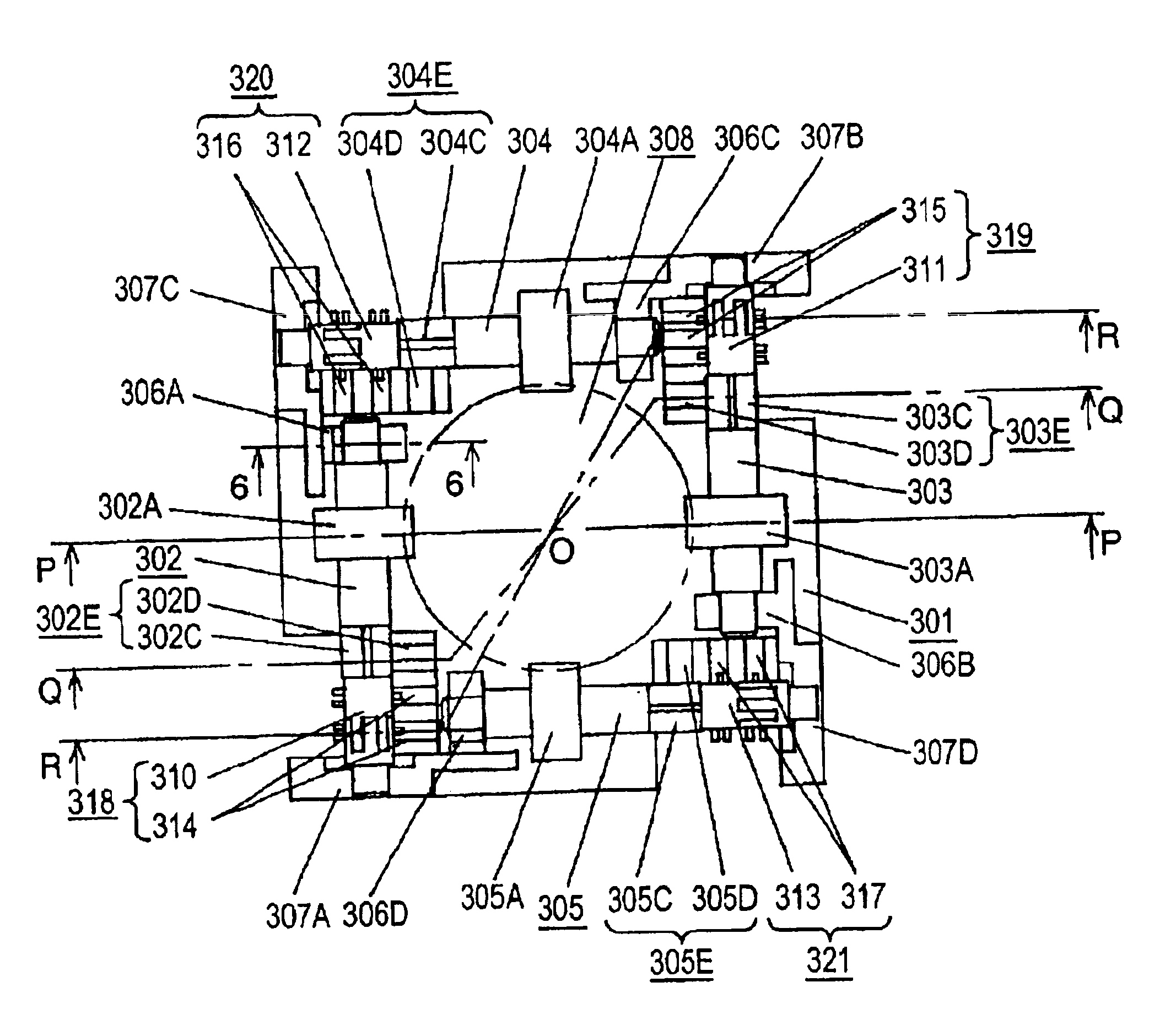
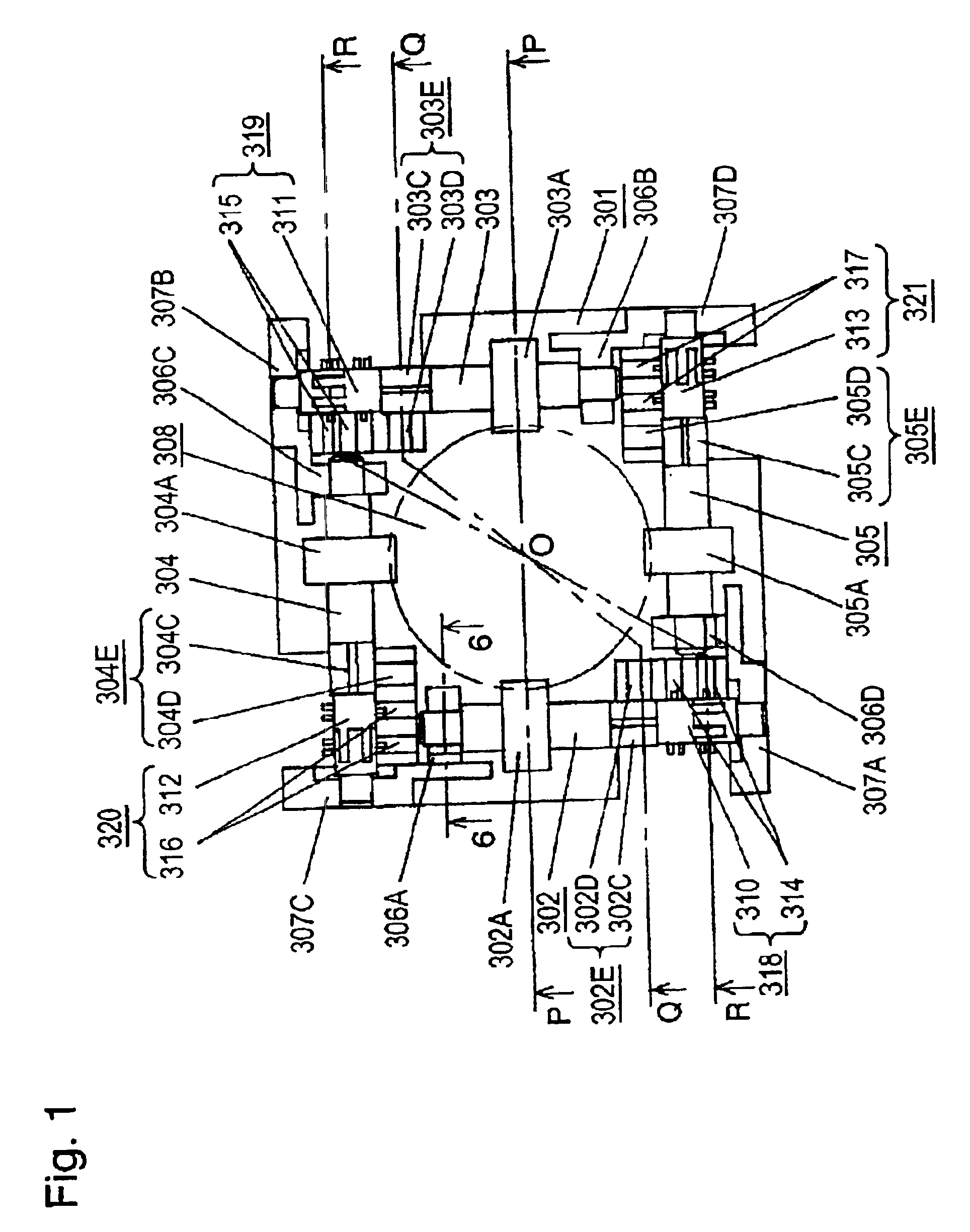
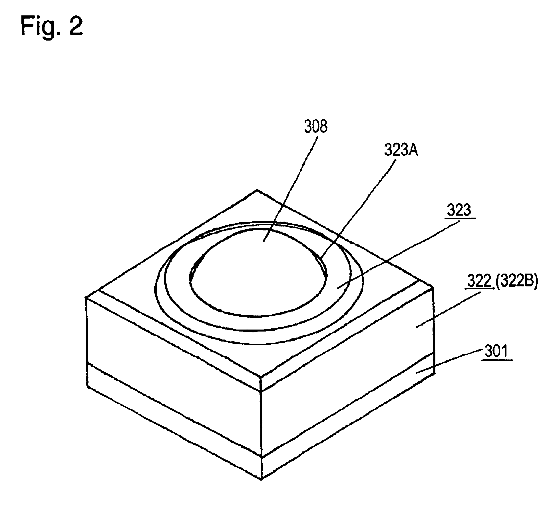
[0064]FIG. 1 is a plan view of a track ball device having a case excluded according to embodiment 1 of the present invention, and FIG. 2 is a perspective outline view of the device. FIG. 3 to FIG. 5 are sectional views at cut lines in FIG. 1 of the track ball device having the case, and specifically FIG. 3 is a sectional view at a line P-O-P, FIG. 4 is a sectional view at a line Q-O-Q, and FIG. 5 is a sectional view at a line R-O-R.

[0065]A base unit 301 of the track ball device is made of resin in a square shape as seen from the top. Near each side of the top of the base unit 301, as shown in FIG. 1 and FIG. 3, four circular shaft, an XI roller 302, XII roller 303, YI roller 304, and YII roller 305 are disposed as two groups of two opposing rollers are disposed in orthogonal to each other. On the base unit 301, support units 306A to 306D, and support units 307A to 307D are formed unitarily with the base unit at the same height while two of the units are formed for one ...

embodiment 2

(Embodiment 2)

[0093]FIG. 9 is a plan of a track ball device having a case excluded according to embodiment 2 of the invention. FIG. 10 and FIG. 11 are sectional views of the track ball device having the case. FIG. 10 is a sectional view at a line T-O-T, and FIG. 11 is a sectional view at a line U-O-U.

[0094]Similarly to embodiment 1, a track ball device in this embodiment has four circular shaft XI roller 325, XII roller 326, and YI roller 327, YII roller 328 disposed in two sets of two opposing rollers in orthogonal to each other on the top of a square base unit 324 made of resin. The base unit 324 has support units 329A to 329D, and support units 330A to 330D formed at two positions for one roller unitarily with the base unit at the same height. The rollers are rotatably supported by the support units. At a slightly lower position than the center of a ball 308, an operating element, contacting portions 325A to 328A having circular sections contact on the outer circumference of the ...

embodiment 3

(Embodiment 3)

[0114]FIG. 15 is a sectional view of a track ball device in embodiment 3 of the invention, and FIG. 16 is a sectional view of the operated track ball device.

[0115]Similarly to embodiment 1, the track ball device of this embodiment includes four circular shaft rollers disposed in two sets of two opposing rollers in orthogonal to each other on the top of a base unit 324 made of resin. In FIG. 15 and FIG. 16, only XI roller 325 and XII roller 326 of the four rollers are shown.

[0116]The track ball device of this embodiment has the ball 308 easily rotatably supported in a dish 322D at a center of a bowl unit 322A of a case 322. While not being manipulated, the ball 308 does not contact with contacting portions 325A, 326A, so that gaps 360, 361 can be formed between the ball 308 and the contacting portions 325A, 326A of the rollers 325, 326.

[0117]As shown in FIG. 16, when the track ball device is manipulated, the ball 308 is pushed with a finger 362 of a user, and contacts w...


PUM


Abstract

Relating to a track ball device for manipulating a cursor moving on a display screen of an electronic apparatus, a track ball device being manipulated precisely while generating a click feel when a ball is rotated, having a small play angle and small size is presented. Beneath the center of the ball, the ball is rotatably supported by four rollers. The section of a contacting portion of the rollers contacting with the ball is a circular sawtooth profile, and the directions of the sawtooth serrations of opposite rollers are reverse to each other. Rollers 2 to 5 have switches as rotation amount detecting units. Further, X roller and Y roller contacting with the outer circumference in the orthogonal direction as seen from above the ball, and third roller hold the ball rotatably. Plural undulations are formed on the outer circumference of large-diameter contacting portions of the X roller and Y roller 3 of circular shaft shape. Rotary encoders are coupled to individual rollers.

Description

TECHNICAL FIELD[0001]The present invention relates to a track ball device for manipulating a cursor moving on a display screen of an electronic apparatus, and an electronic apparatus using the device.BACKGROUND ART[0002]FIG. 50 is a perspective view showing a configuration of a conventional track ball device. A ball 151, an operating element, is held in a main body (not shown) so as to be rotated freely in all directions when having a surface touched by a hand or finger of an operator. On the outer circumference of the ball, rollers 152 and 153 contacts in orthogonal directions from a top view. Rotary encoders 154 and 155 of two-signal type capable of distinguishing the direction of the rotation are coupled to the rollers 152 and 153 as means for detecting the direction and amount of rotation.[0003]When the ball 151 is rotated by the hand or finger, the rollers 152 and 153 rotate, and the rotary encoders 154 and 155 detect the direction and amount of rotation in an X-axis direction ...

Claims


Application Information

Patent Timeline
Patent Type & Authority Patents(United States)
IPC IPC(8): G06F3/033G06F3/0354
CPCG06F3/03549G06F3/0312G06F3/0354
Inventor YOKOJI, SHIGERUYAMAMOTO, TAMOTSUNAKASE, MASAKIFUKUMURA, TOYOSHI
Owner PANASONIC CORP
Why Eureka
Try Eureka