

Image forming system with scanner capable of changing magnification of scanned image
a technology of scanning system and scanner, applied in the field of image forming apparatus, can solve problems such as the writing position in the sub-scanning direction
- Summary
- Abstract
- Description
- Claims
- Application Information
AI Technical Summary
Benefits of technology
Problems solved by technology
Method used
Image

Examples
first embodiment
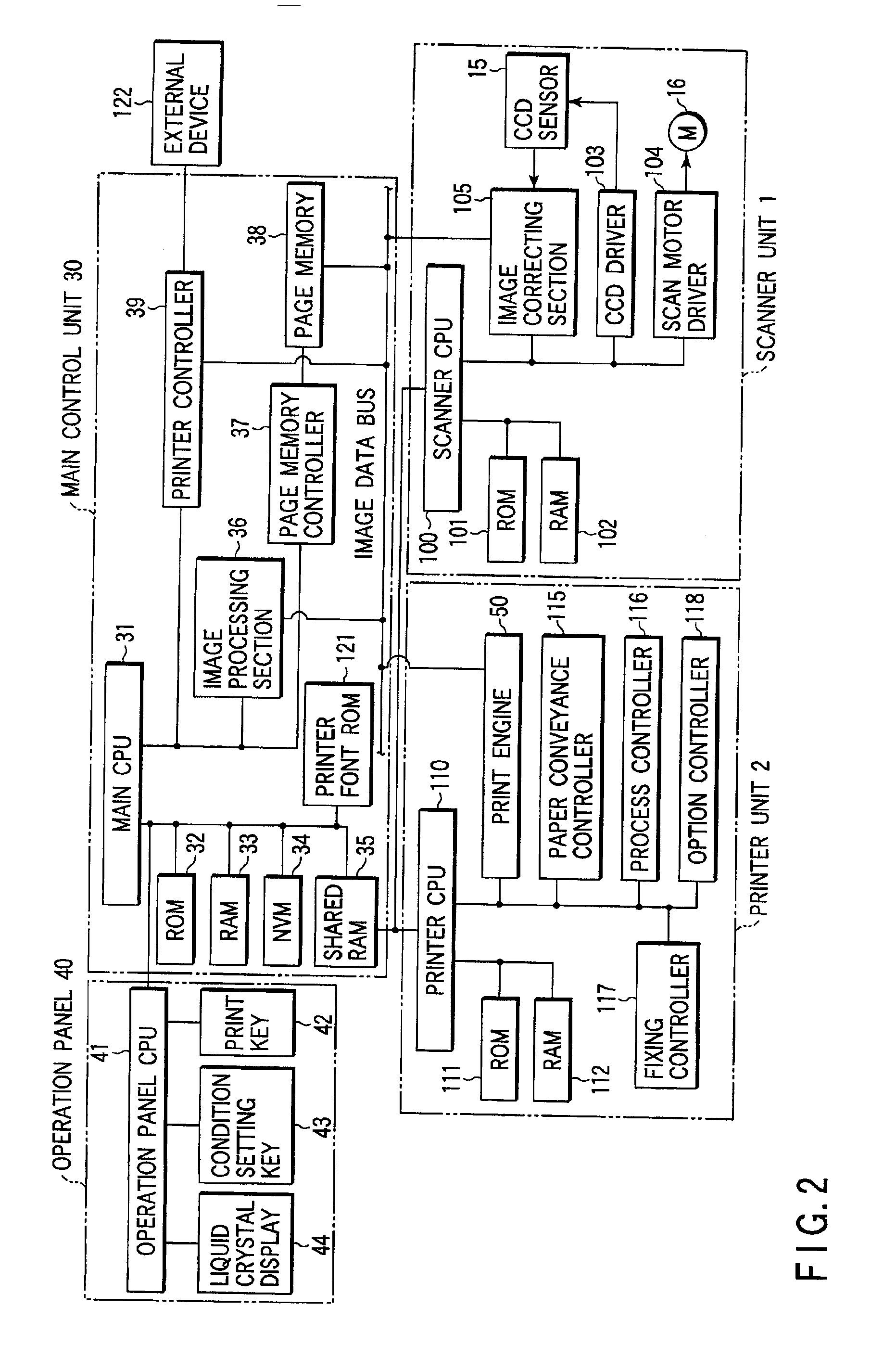
[0093][2] The control system according to the present invention will now be described with reference to FIGS. 5, 7 and 9.
[0094]FIG. 5 is a diagram showing an internal structure (example 1) of the CCD sensor and the image correcting section included in the scanner unit illustrated in FIG. 2.
[0095]The CCD sensor 15 includes an R line sensor 451 for red color, a G line sensor 452 for green color, and a B line sensor 453 for blue color. Each of the line sensors is constituted by a number of photoelectric converting elements (CCD elements) arranged in line in the longitudinal direction. An R filter 454 through which red-colored optical components pass selectively is provided on the light-receiving surface of the R line sensor 451, a G filter 455 through which green-colored optical components pass selectively is provided on the light-receiving surface of the G line sensor 452, and a B filter 456 through which blue-colored optical components pass selectively is provided on the light-receiv...
second embodiment
[0127][3] The control system according to the present invention will now be described with reference to FIGS. 6, 8 and 10.
[0128]FIG. 6 is a diagram showing an internal structure (example 2) of the CCD sensor and the image correcting section included in the scanner unit illustrated in FIG. 2. The circuit arrangement of FIG. 6 differs from that of FIG. 5 in that a delay memory 570 is arranged in the final stage. The elements common to the circuit arrangements shown in FIGS. 5 and 6 have the same functions, operations and features.
[0129]A characteristic portion of the circuit arrangement of FIG. 6 (that the circuit arrangement of FIG. 5 does not have) will be discussed hereinafter.
[0130]According to the embodiment shown in FIG. 6, when the scanning magnification is 400%, an image delay of 48 lines is required as described above with reference to FIG. 5. It is the delay memory 570 that causes the 48-line delay. A delay amount of 64 lines, which is equal to the sum of that of 48 lines in...
PUM
 Abstract
Description
Claims
Application Information