Method and system for reducing thermal pole tip protrusion
- Summary
- Abstract
- Description
- Claims
- Application Information
AI Technical Summary
Benefits of technology
Problems solved by technology
Method used
Image

Examples
first embodiment
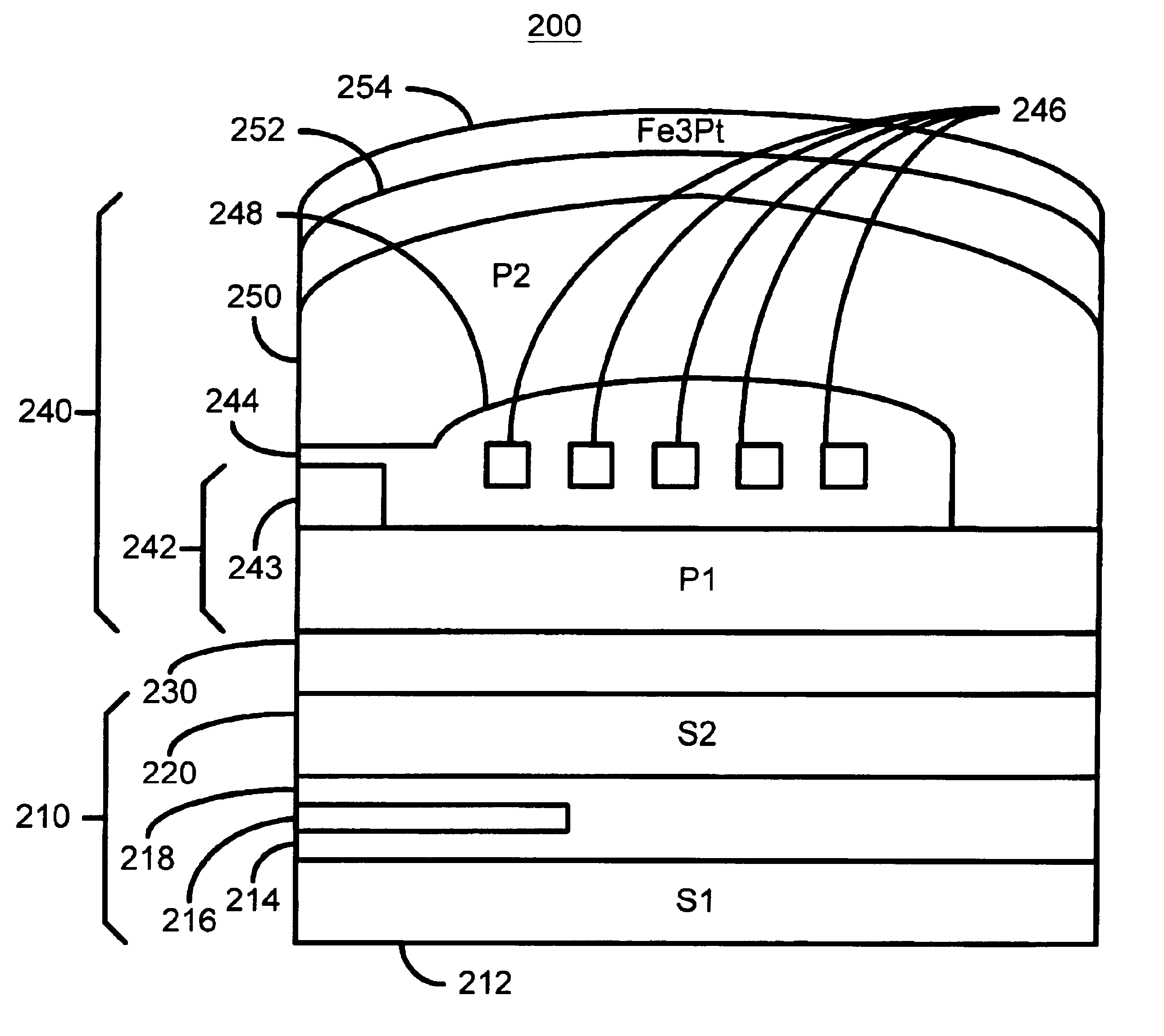
[0024]FIG. 3 is a side view of a portion of a merged head 200 including write head in accordance with the present invention having reduced thermal pole tip protrusion. The merged head 200 includes a read head 210 and a write head 240. The read head 210 includes S1212, a first gap 214, a read sensor 216, a second gap 218 and S2220. The S2220 of the read head 210 is separated from the write head 240 by a gap 230. The write head 240 includes a P1242 having a pedestal 243, a coil 246 surrounded by insulator 248, and a P2250. A portion of P2250 is separated from the pedestal 243 of the P1242 by a write gap 244. In addition, the merged head 200 includes Fe3Pt INVAR 254 separated from P2250 by a gap 252 that is preferably insulating and nonmagnetic. The Fe3Pt INVAR is thus magnetically decoupled from the coil 246, as well as the poles 242 and 250.
second embodiment
[0025]FIG. 4 is a side view of a portion of a merged head 200′ including a write head 240′ in accordance with the present invention having reduced thermal pole tip protrusion. The merged head 200′ has components which are analogous to the merged head 200 depicted in FIG. 3. These components are numbered similarly. For example, the merged head 200′ includes read head 210′ and write head 240′ corresponding to the read head 210 and write head 240 of FIG. 3. Referring back to FIG. 4, the merged head 200′ includes gaps 230′ and 231′ between the read head 210′ and the write head 240′. The Fe3Pt INVAR 254′ resides between the gaps 230′ and 231′. Thus, the Fe3Pt INVAR 254′ is between S2220′ and P1242′. Because it is separated using the gaps 230′ and 231, the Fe3Pt INVAR is magnetically decoupled from the coil 246′ as well as the poles 242′ and 250′.
third embodiment
[0026]FIG. 5 is a side view of a portion of a merged head 200″ including a write head 240″ in accordance with the present invention having reduced thermal pole tip protrusion. The merged head 200″ has components which are analogous to the merged head 200 depicted in FIG. 3. These components are numbered similarly. For example, the merged head 200″ includes read head 210″ and write head 240″ corresponding to the read head 210 and write head 240 of FIG. 3. The Fe3Pt INVAR 254″ resides below S1212″ and separated by gap 252″. Because it is separated using the gap 252″, the Fe3Pt INVAR 254″ is magnetically decoupled from the coil 246″ as well as the poles 242″ and 250″.
PUM
 Abstract
Description
Claims
Application Information