Image processing method of generating conversion data for a scanner and calibration method employing the scanner

a technology of conversion data and image processing method, which is applied in the direction of instruments, electrical appliances, computing, etc., can solve the problems of inability to supply a printer with an expensive densitometer, the densitometer is relatively expensive, and the printing property may vary among the plurality of printing apparatuses, etc., to achieve high accuracy

Inactive Publication Date: 2005-06-21
CANON KK
View PDF9 Cites 16 Cited by
  • Summary
  • Abstract
  • Description
  • Claims
  • Application Information

AI Technical Summary

Benefits of technology

[0012]An object of the present invention is to make it possible to carry out a calibration of

Problems solved by technology

In a case of an information processing system in which a plurality of printing apparatuses are connected with one another through a network, difference in the printing property among the plurality of printing apparatus may present a problem.
The densitometer, however, is relatively expensive; it is not realistic to supply a printer with an expensive densitometer as peripheral equipment, or to make the user purchase the densitometer separately in order to calibrate a low-price printer.
However, it

Method used


Image

  • Image processing method of generating conversion data for a scanner and calibration method employing the scanner
  • Image processing method of generating conversion data for a scanner and calibration method employing the scanner
  • Image processing method of generating conversion data for a scanner and calibration method employing the scanner

Examples


first embodiment

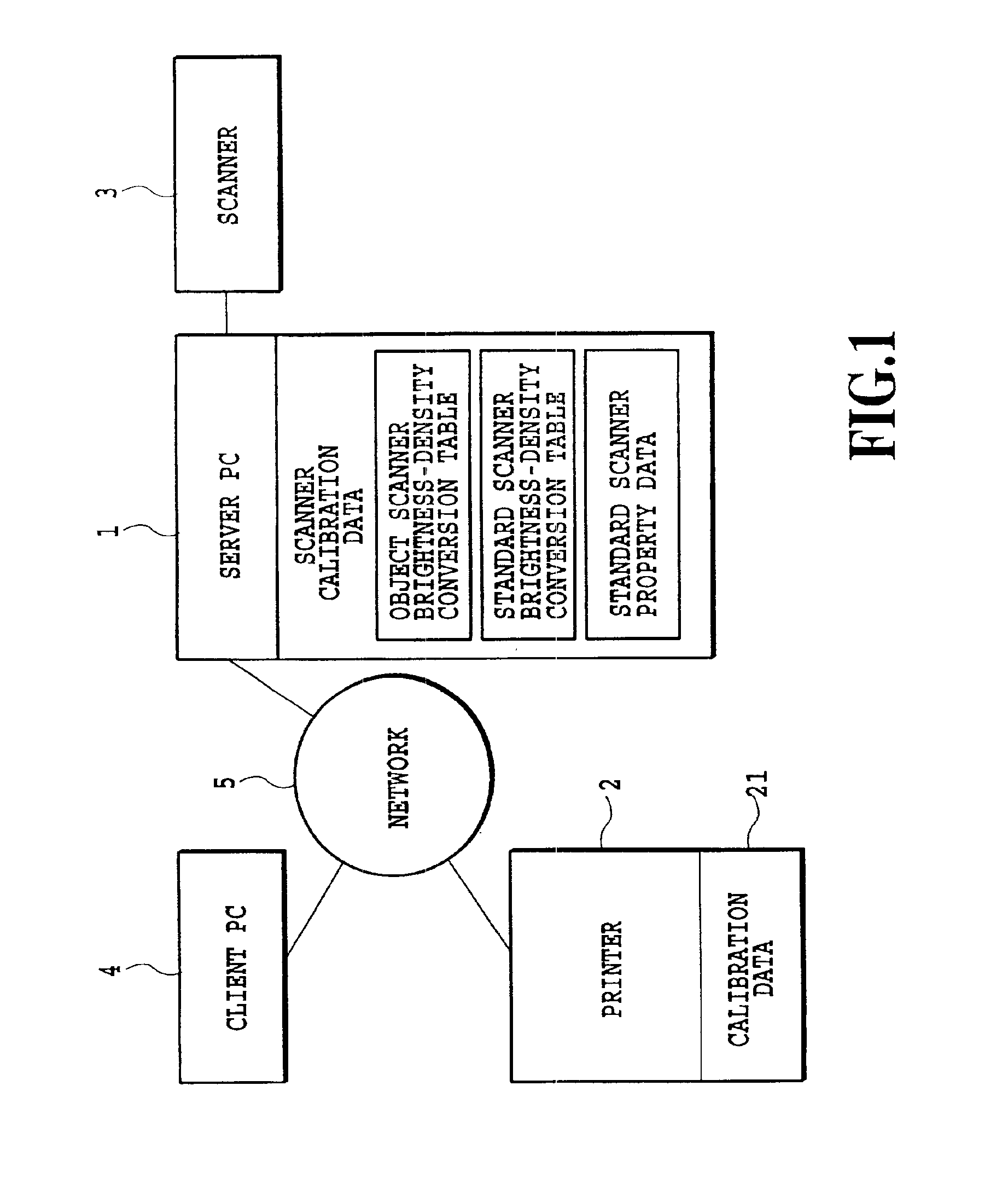
[0065]FIG. 1 is a block diagram showing a configuration of a print system according to the present invention.

[0066]Although in this example a connection form and a protocol in a network as shown in FIG. 1 are not referred to in detail, the present invention may be applied to any connection form or protocol.

[0067]The numeral 1 represents a server PC (Personal Computer), in which software for realizing the system of the embodiment is installed. The server PC 1 is connected to a network 5.

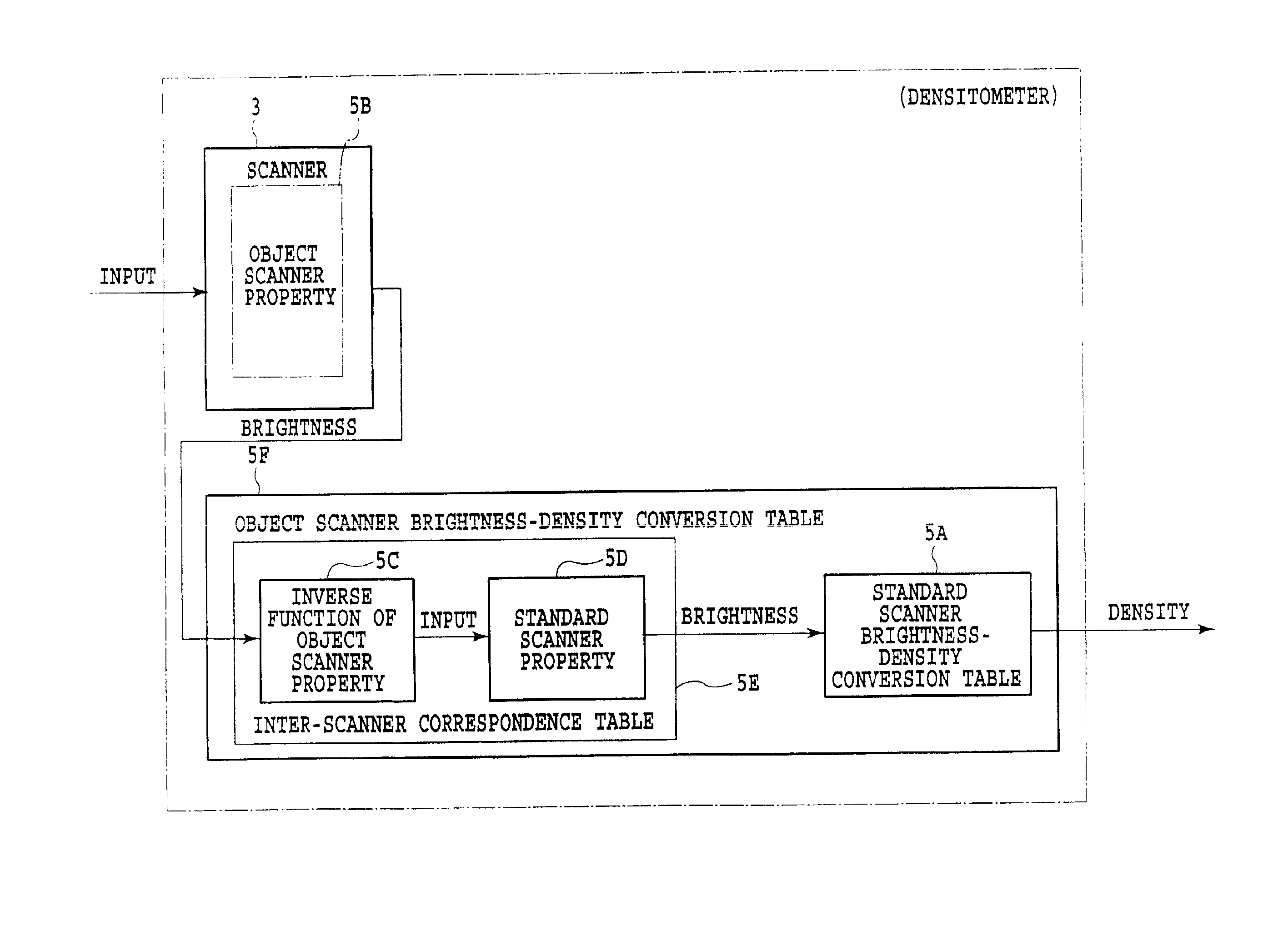
[0068]The numeral 11 represents a scanner calibration data storing section, which is provided in the server PC 1 to store scanner calibration data described below. The numeral 111, within the scanner calibration data storing section 11, represents an object scanner brightness-density conversion table storing section for storing a brightness-density conversion table, which is provided for a scanner which a user employs in this print system (hereinafter “object scanner”) and which is used upon inputting...

second embodiment

[0110]the present invention will be described in detail below.

[0111]In the above-described first embodiment, even if the standard scanner is used as the object scanner for the scanner calibration, the print system is adapted to execute a process of the scanner calibration. In contrast in this embodiment, if the standard scanner is used as the object scanner, the scanner calibration is skipped and the subsequent steps are executed using a standard scanner brightness-density conversion table generated in advance.

[0112]Accordingly, a configuration of the printer calibration in this embodiment is basically the same as in the first embodiment, but differs from the first embodiment in following points. In the embodiment a judgment is made as to whether the scanner for use is a standard scanner or not. When the scanner is judged to be the standard scanner, the step of the scanner calibration is skipped, and then the subsequent steps are executed using the standard scanner brightness-densit...

fourth embodiment

[0138]Although in the fourth embodiment scanner calibration data is prepared for each type of scanners, this is not the only possibility of the present invention; it is possible to prepare the scanner calibration data for each individual scanner of the same type, for instance.

[0139]In this embodiment, the scanner itself possesses the scanner calibration data storing section. Then the calibration data stored in the storing section may be generated each time the printer is calibrated as in the first to third embodiments, or may be obtained and stored in advance as in the fourth embodiment.

[0140]FIG. 21 is a block diagram showing a configuration of a print system according to this embodiment. The system in this embodiment is constituted basically the same as the system shown in FIG. 1 of the first embodiment; the difference is that the scanner 3 stores the scanner calibration data in this embodiment.

[0141]In this embodiment too, under control of the server PC 1, the printer 2 is calibr...


PUM


Abstract

A calibration for a scanner, which is used as a densitometer, is carried out always with high accuracy. More specifically, an image processing method of generating a conversion condition for a scanner which is used for reading an image and generating image data, is provided. The method including the steps of: obtaining a reading property of an object scanner based on image data obtained by that the object scanner reads a chart, and generating the conversion condition for the object scanner based on the reading property of the object scanner, a previously prepared reading property of a standard scanner and a previously prepared brightness-density conversion condition for the standard scanner.

Description

[0001]This application is based on Japanese Patent Application Nos. 11-(263920 and 11-(264634 both filed Sep. 17, 1999, the content of which is incorporated hereinto by reference.BACKGROUND OF THE INVENTION[0002]1. Field of the Invention[0003]The present invention relates to an image processing method of generating conversion data for a scanner, and to a calibration method of calibrating a printing apparatus by means of the scanner.[0004]2. Description of the Prior Art[0005]It is generally known that a printing property of a printing apparatus may vary according to a surrounding condition such as a temperature and a humidity of a surrounding air, in which the printing apparatus is used. Not only the surrounding condition but also use of the printing apparatus for a certain period of time may cause the printing property to vary. In a case of electrophotographic printing apparatus, for instance, a photosensitive property of a photosensitive drum changes according to the surrounding co...

Claims


Application Information

Patent Timeline
IPC IPC(8): G06K9/40H04N1/46H04N1/60
CPCH04N1/6033
Inventor NAKAJIMA, NOBUYUKI
Owner CANON KK
Why Eureka
Try Eureka