Method and device for measuring a temperature variable in a mass flow pipe

a technology of mass flow and temperature variable, which is applied in the direction of position/direction control, digital computer details, special data processing applications, etc., can solve the problems of saving complexity and cost to a considerable exten

Inactive Publication Date: 2005-06-21
ROBERT BOSCH GMBH
View PDF12 Cites 18 Cited by
  • Summary
  • Abstract
  • Description
  • Claims
  • Application Information

AI Technical Summary

Benefits of technology

[0007]In this way, complexity and cost are saved to a considerable extent.
[0009]It is especially advantageous that the modeled signal is attenuated by means of a filter, preferably, a lowpass filter, in order to avoid a signal which is too noisy. Here, in an advantageous manner, the time constant of the filter is adapted to the portion of the introduced gas flow in the total flow. The time constant is that much greater the higher this rate is. In this way, the influence of inaccuracies and fluctuations of this portion is significantly reduced.

Problems solved by technology

In this way, complexity and cost are saved to a considerable extent.

Method used


Image

  • Method and device for measuring a temperature variable in a mass flow pipe
  • Method and device for measuring a temperature variable in a mass flow pipe
  • Method and device for measuring a temperature variable in a mass flow pipe

Examples


Embodiment Construction

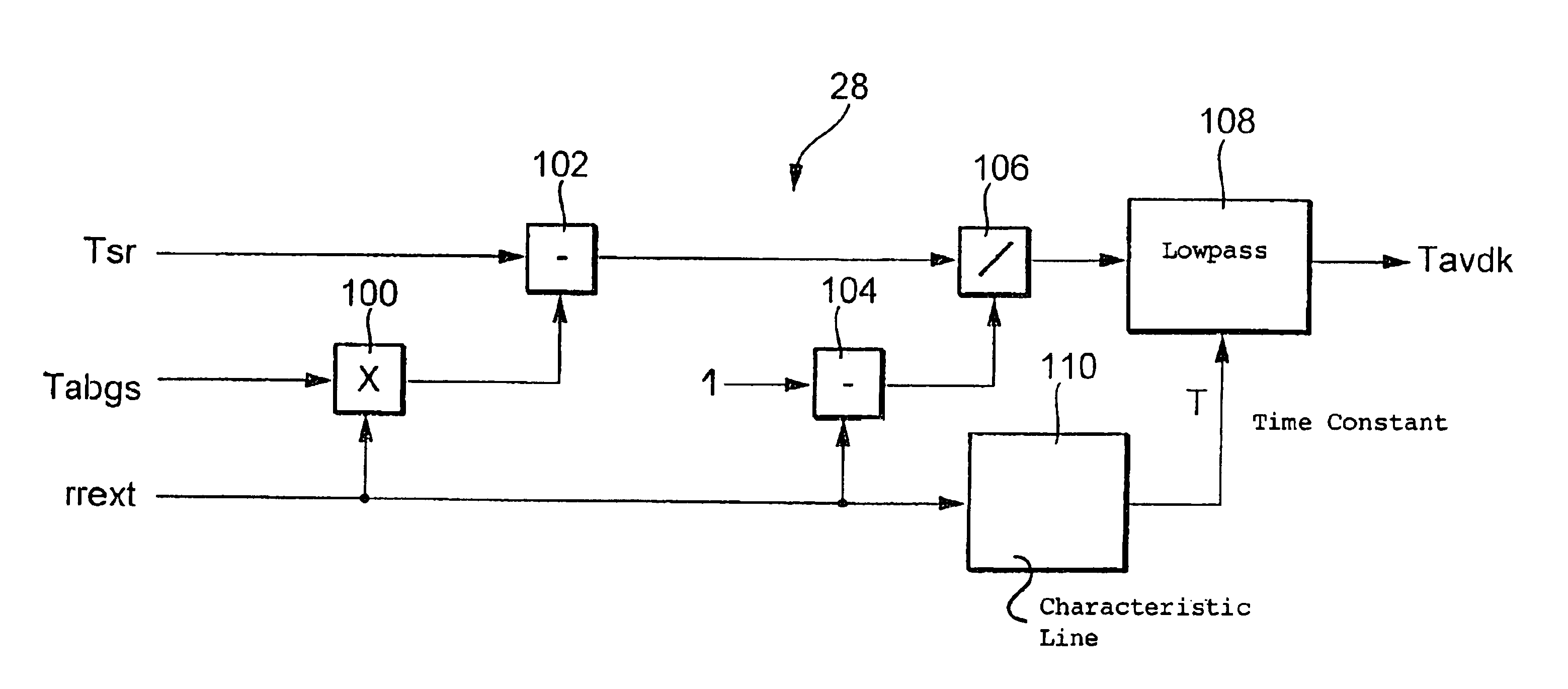
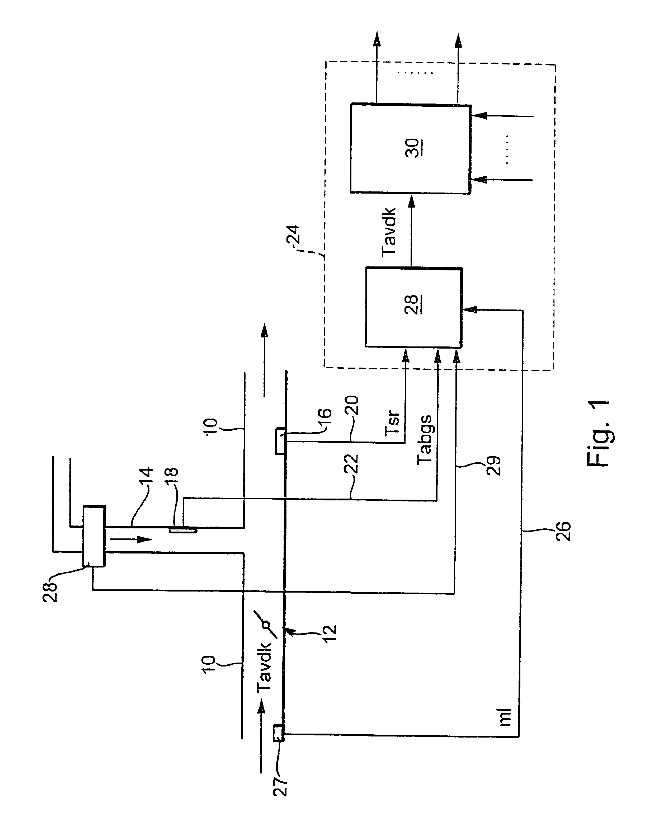
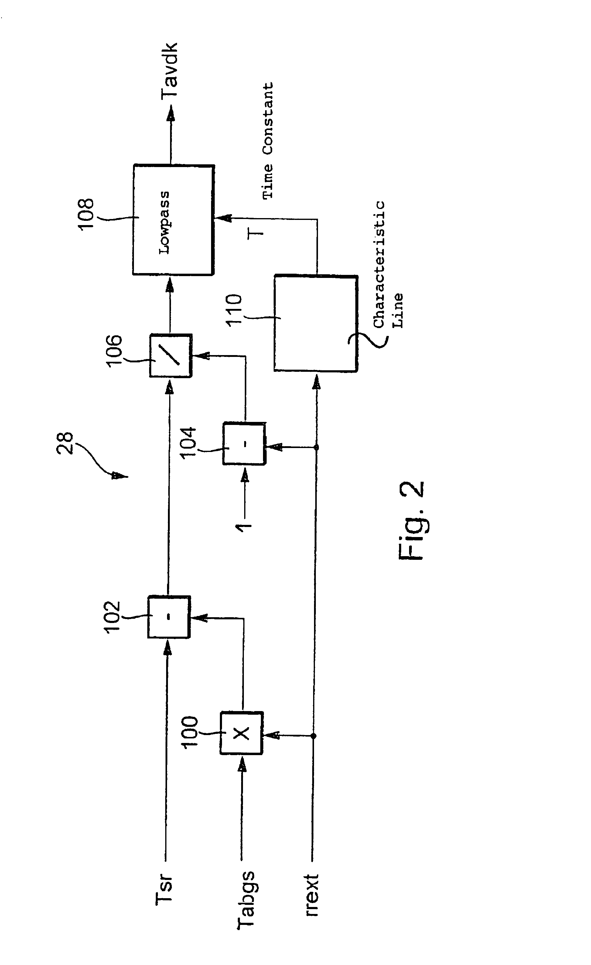
[0015]In FIG. 1, 10 identifies a mass flow line having a throttle position 12 and a further mass flow line 14 which opens into the mass flow line 10 after the throttle position in order to introduce an additional gas flow. In the preferred embodiment of an internal combustion engine, the mass flow line 10 defines the intake manifold and the throttle position 12 defines the throttle flap and the additional mass flow line 14 is the exhaust-gas recirculation line. Corresponding to the arrows shown in FIG. 1, a gas flow flows into the mass flow line 10 from left to right and in the mass flow line 14 from top to bottom. Furthermore, a first temperature sensor 16 is provided which supplies the temperature of the flowing gas in the mass flow line 10 downstream of the introduction of the additional mass flow. In one embodiment, a further temperature sensor 18 measures the temperature of the in-flowing gas flow in the mass flow line 14. The corresponding temperature signals Tsr and Tabgs are...


PUM

PropertyMeasurementUnit
temperatureaaaaaaaaaa
mass flowaaaaaaaaaa
massaaaaaaaaaa

Abstract

A method and an arrangement are suggested for determining a temperature quantity in a mass flow line which includes a throttle position and to which an additional gas mass flow is supplied after the throttle position. The temperature ahead of the throttle position is determined on the basis of the portion of the additional gas mass flow in the total flow in dependence upon the temperature of the mixture of the two gas mass flows as well as the temperature of the introduced gas mass flow.

Description

FIELD OF THE INVENTION[0001]The invention relates to a method and an arrangement for determining a temperature variable in a mass flow line.BACKGROUND OF THE INVENTION[0002]In some applications, for example in the context of motor vehicle technology (the engine control), it is of significance to know which temperature is present in a mass flow line provided with a throttle valve. In such an engine control, such temperature values are evaluated in the determination of actuating quantities of the engine in dependence upon an input value (see, for example, DE-A 196 18 385). A further application of the evaluation of such a temperature value is defined by the formation of actual quantities in the context of the engine control, for example, in the context of load detection (see, for example, U.S. Pat. No. 6,588,261). The temperature of the in-flowing gas ahead of the throttle position is of interest especially for considering the instantaneous density of the gas.[0003]The determination o...

Claims


Application Information

Patent Timeline
Patent Type & Authority Patents(United States)
IPC IPC(8): F02D21/00F02D21/08G01K7/42F02M25/07F02D45/00F02M26/00F02M26/47
CPCF02D41/0072G01K7/42F02M25/0754F02D2041/0067F02D2200/0414Y02T10/47F02M2025/0762F02M26/47F02M2026/004Y02T10/40
Inventor WILD, ERNSTFALK, MARIO
Owner ROBERT BOSCH GMBH
Why Eureka
Try Eureka