Helmet

a technology for helmets and helmet covers, applied in the field of helmets, can solve the problems of ineffective ventilation of the interior of the head protecting body, and ineffective fogging prevention of the shield plate, etc., and achieves the effects of simple structure, easy opening and closing, and effective discharge to the outsid

Inactive Publication Date: 2005-06-28
SHOEI CO LTD
View PDF9 Cites 28 Cited by
  • Summary
  • Abstract
  • Description
  • Claims
  • Application Information

AI Technical Summary

Benefits of technology

[0012]According to the first aspect of the present invention, a ventilation opening serving as an exhaust opening of the ventilator mechanism is formed in the step surface of the stabilizer portion, and the step surface having the ventilator opening extends from near a rear end of the air current deflection surface substantially toward the outer surface of the head protecting body. Accordingly, the outer side of the exhaust opening is at a negative pressure, so that air in the head protecting body can be discharged well to the outside from the ventilation opening. Air in the head protecting body can be effectively discharged to the outside from the exhaust opening with a relatively simple structure.
[0013]According to the first and second aspects of the present invention, the traveling wind flowing along the outer surface of the head protecting body is forcibly separated from the outer surface of the head protecting body by the air current deflection surface of the stabilizer portion, and shifts relatively backward while it maintains a substantially laminar state. As the amount of traveling wind abruptly detouring to the rear portion of the head protecting body can be decreased, the drag and lift with respect to the head protecting body can be decreased. As a result, the traveling stability of the head protecting body can be achieved with a comparatively simple arrangement.
[0015]According to the first embodiment of the second aspect and the third aspect of the present invention, in addition to the ventilation opening of the air current divider portion which serves as the first exhaust opening of the ventilator mechanism, a second ventilation opening serving as a second exhaust opening of the ventilator mechanism is formed in the step surface of the stabilizer portion or ventilation opening forming portion, and the step surface having the ventilator opening extends from near a rear end of the air current deflection surface substantially toward the outer surface of the head protecting body. Accordingly, the outer side of the second exhaust opening is also at a negative pressure, so that air in the head protecting body can be discharged well to the outside from the second ventilation opening as well. Air in the head protecting body can be discharged to the outside more effectively from the two types of exhaust openings (i.e., first and second exhaust openings) with a relatively simple structure.
[0016]Furthermore, according to the second embodiment of the second aspect and the first embodiment of the third aspect of the present invention, the first exhaust path having the first exhaust opening as the terminal end and the second exhaust path having the second exhaust opening as the terminal end can be commonly opened and closed by a common shutter mechanism. Hence, these two types of exhaust paths (i.e., first and second exhaust paths) can be opened and closed easily.
[0017]According to the third embodiment of the second aspect and the second embodiment of the third aspect of the present invention, each of the first and second exhaust paths has a pair of left and right exhaust paths. Therefore, air in the head protecting body can be discharged to the outside more effectively. The pair of left and right first exhaust paths and the pair of left and right second exhaust paths can be commonly opened and closed by the common shutter mechanism. Therefore, these two types of exhaust paths, amounting to a total of four, can be opened and closed very easily.
[0018]According to the fourth embodiment of the second aspect and the third embodiment of the third aspect of the present invention, the arrangement and operation of the shutter mechanism can be simplified.

Problems solved by technology

In the conventional helmet with the above arrangement, however, the outer air introduced into the head protecting body through the forehead air supply hole merely diffuses naturally over a wide range in the head protecting body, and draft for ventilation of the interior of the head protecting body and the like cannot be performed effectively.
Thus, fogging of the shield plate cannot be prevented well.
Therefore, with the conventional helmet, when it rains and the humidity is very high, ventilation of the interior of the head protecting body and fogging prevention of the shield plate cannot be performed effectively.

Method used


Image

  • Helmet
  • Helmet
  • Helmet

Examples


first embodiment

1. First Embodiment

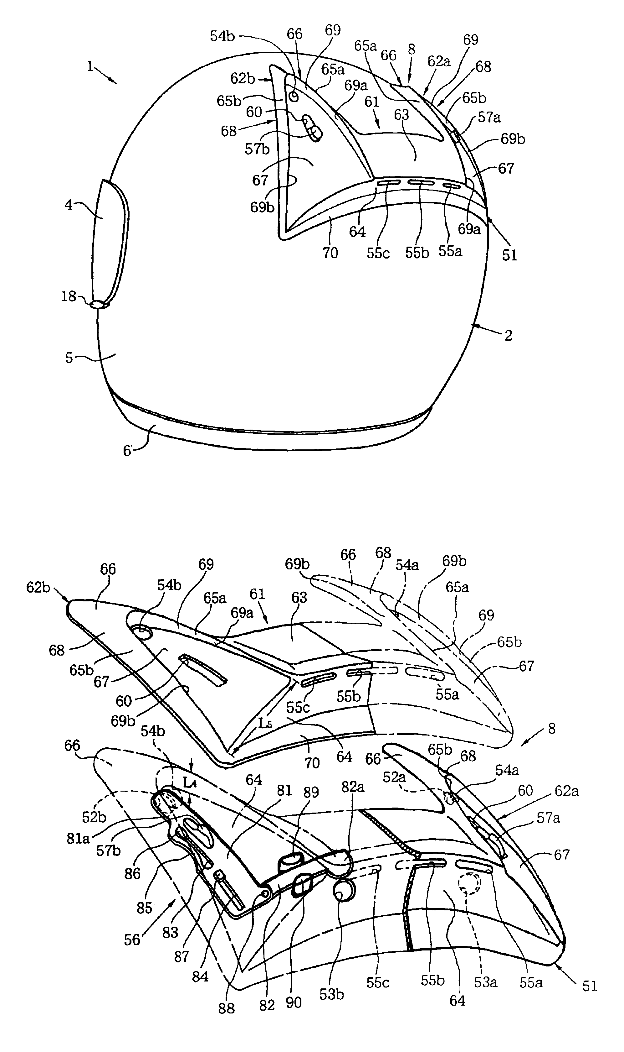
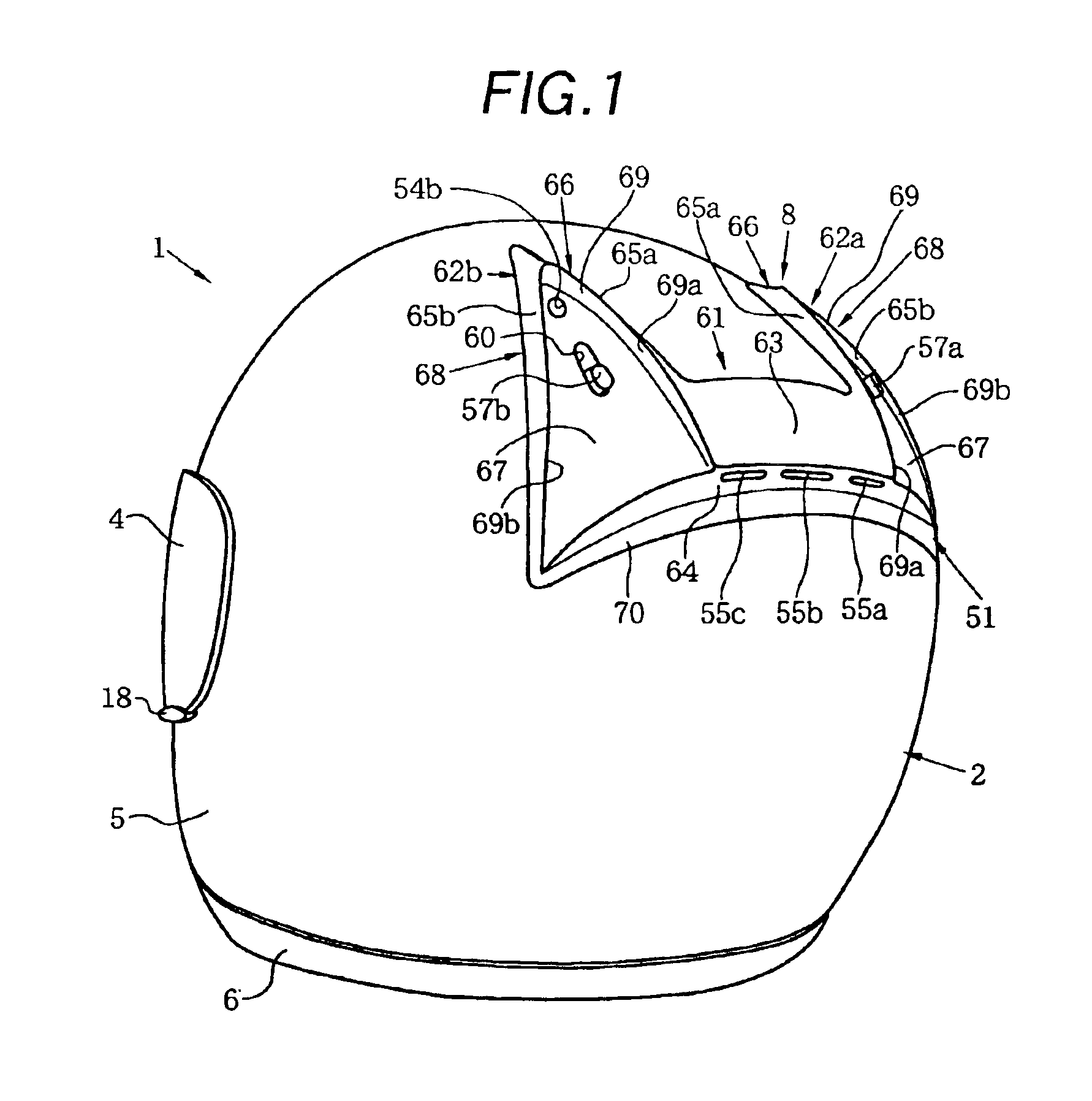
[0039]The first embodiment will be sequentially described separately into “entire helmet”, “impact-on-the-head and impact-on-the-chin-and-cheek absorbing liners”, “forehead and chin ventilator mechanisms” and “back head side ventilator mechanism” with reference to FIGS. 1 to 10.

(1) Entire Helmet

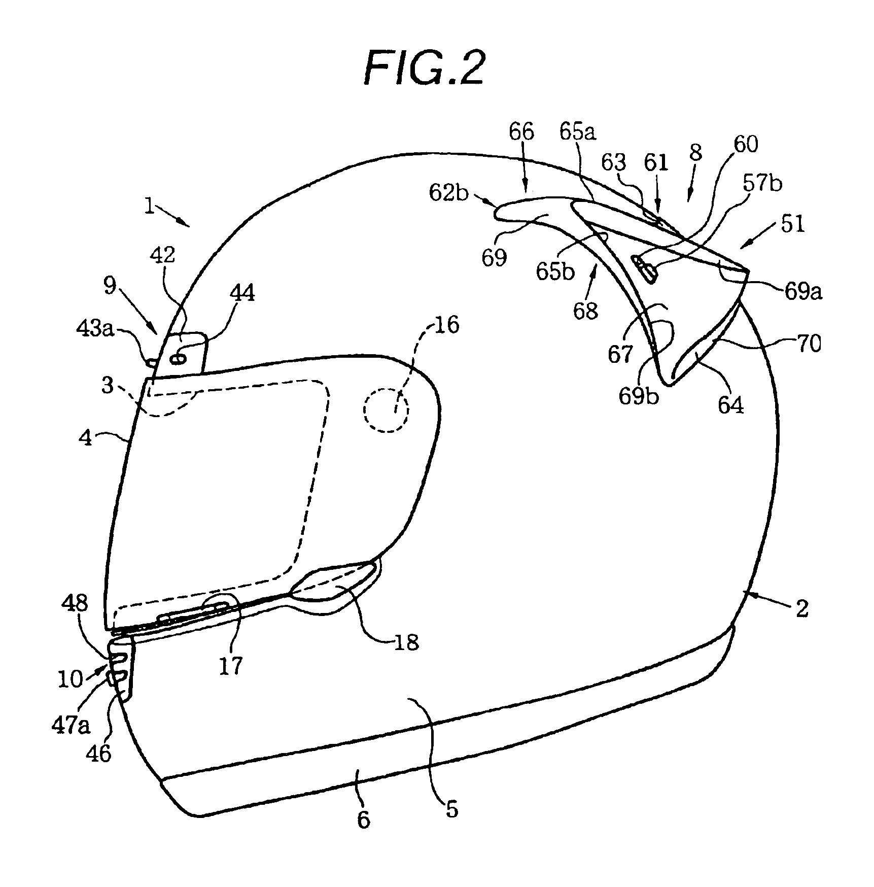
[0040]As shown in FIGS. 1 to 4, a full-face-type helmet 1 is made up of a full-face-type cap-like head protecting body 2 to be worn on the head of a wearer, a shield plate 4 capable of opening / closing a window opening 3 which is formed in the front surface of the head protecting body 2 to oppose that portion (i.e., the face) of the wearer, which is between the forehead and chin, and a pair of left and right chin straps (not shown in FIGS. 1 to 4 as they are accommodated in the head protecting body 2 and can be conventional ones) attached to the inner side of the head protecting body 2. A forehead ventilator mechanism 9 is formed at at least a part of the forehead region of ...

second embodiment

2. Second Embodiment

[0090]The second embodiment will be described with reference to FIGS. 11 to 18. The second embodiment can be substantially the same as the first embodiment described above except that

[0091](1) a front head side ventilator mechanism 91 is newly added,

[0092](2) the practical structure of shutter mechanisms 56 of a back head side ventilator mechanism 8 is different,

[0093](3) the practical shape of a ventilation opening forming member 51 serving also as a stabilizer constituting member is slightly different,

[0094](4) a pair of left and right ventilation openings 92a and 92b are newly formed in the lower portion of the occiput region of an outer shell 5, and

[0095](5) the arrangements of ventilation openings and ridge grooves formed in the outer shell 5 and in an impact-on-the-head absorbing liner 11 are slightly different. Hence, in the following description, only these differences will be described separately, and a description on portions that are common to the firs...

third embodiment

3. Third Embodiment

[0120]The third embodiment will be described with reference to FIG. 19. The third embodiment can be substantially the same as the first embodiment described above except that the practical structure of a shutter mechanism 56 of a back head side ventilator mechanism 8 is different and accordingly the practical shape of a ventilation opening forming member 51 serving also as a stabilizer constituting member is slightly different. Hence, in the following description, only these differences will be described, and a description on portions that are common to the first and third embodiments will be omitted.

[0121]The shutter mechanism 56 can close or open all of a pair of left and right ventilation openings 52a and 52b and a pair of left and right ventilation openings 53a and 53b simultaneously by moving a single operating tap 131a of a single operating member 131 forward and backward. The shutter mechanism 56 has the single operating member 131, an attaching plate or at...


PUM


Abstract

A stabilizer constituting member or ventilation opening forming member 51 having a stabilizer portion or ventilation opening forming portion 61, which has an air current deflection surface 63 gradually separating from an outer surface of a head protecting body in the range of the front end to the rear end of the stabilizer portion or ventilation opening forming portion 61, is disposed on an outer side of the head protecting body. According to one aspect, exhaust openings 55a to 55c are formed in a step surface 64 extending from near the rear end of the air current deflection surface 63 substantially toward the outer surface of the head protecting body. According to another aspect, the ventilation opening forming member 51 further has air current divider portions 62a and 62b having exhaust openings 54a and 54b surrounded by substantially two-way forked projecting ridges 66, respectively.Thus, air in the head protecting body can be effectively discharged from the exhaust openings 55a to 55c and / or 54a and 54b. According to the other aspect, the traveling stability of the head protecting body can be achieved.

Description

TECHNICAL FIELD[0001]The present invention relates to a helmet which comprises a head protecting body to be worn on the head of a helmet wearer (to be merely referred to as a “wearer” hereinafter) such as the rider of a motor cycle to protect his / her head, and in which a ventilator mechanism for ventilation of the interior of the head protecting body and the like is provided to the head protecting body.BACKGROUND ART[0002]As a full-face-type helmet having a ventilator mechanism in its head protecting body for the purpose of ventilation of the interior of the head protecting body or fogging prevention of the inner surface of a shield plate, for example, one described in U.S. Pat. No. 5,093,938 is conventionally known.[0003]The full-face-type helmet (to be merely referred to as “the conventional helmet” hereinafter). described in U.S. Pat. No. 5,093,938 has a forehead ventilator mechanism and chin ventilator mechanism above and under a window opening, which is formed in a full-face-ty...

Claims


Application Information

Patent Timeline
Patent Type & Authority Patents(United States)
IPC IPC(8): A42B3/04A42B3/28
CPCA42B3/283A42B3/0493A42B3/28
Inventor TANAKA, HARUO
Owner SHOEI CO LTD
Why Eureka
Try Eureka