Door hold open and controlled release mechanism

Inactive Publication Date: 2005-06-28
CRAWFORD ALAN
View PDF26 Cites 45 Cited by
  • Summary
  • Abstract
  • Description
  • Claims
  • Application Information

AI Technical Summary

Benefits of technology

[0015]In another embodiment, the catch member further comprises a second ramp section and the catch release mechanism further comprises a wedge, the second ramp section and the wedge being arranged such that when the catch release mechanism is moved the wedge engages the second ramp section thereby causing deflection of the catch member thus allowing release of the door closer rod from the hold section of the catch member. In yet another embodiment, the catch release mechanism further comprises a joint and a stop wherein the

Problems solved by technology

These operations are cumbersome and inconveni

Method used


Image

  • Door hold open and controlled release mechanism
  • Door hold open and controlled release mechanism
  • Door hold open and controlled release mechanism

Examples


Embodiment Construction

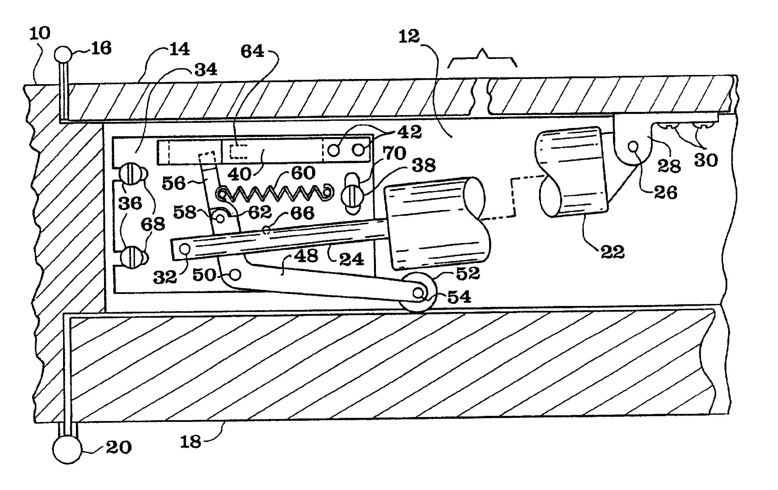
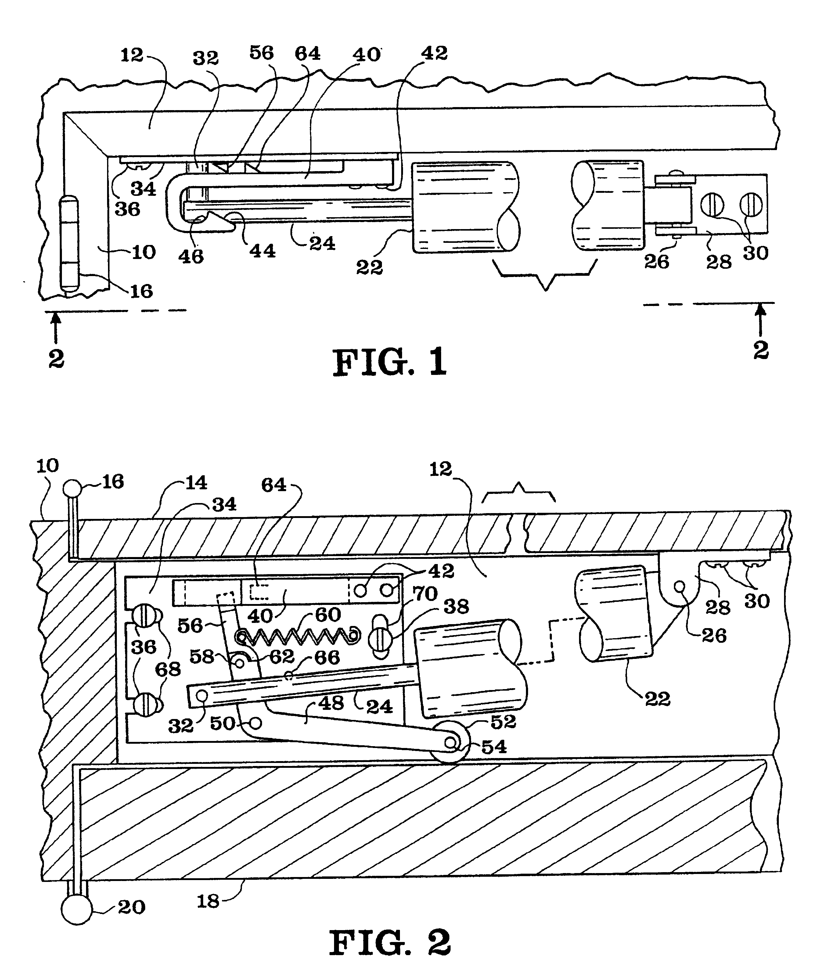
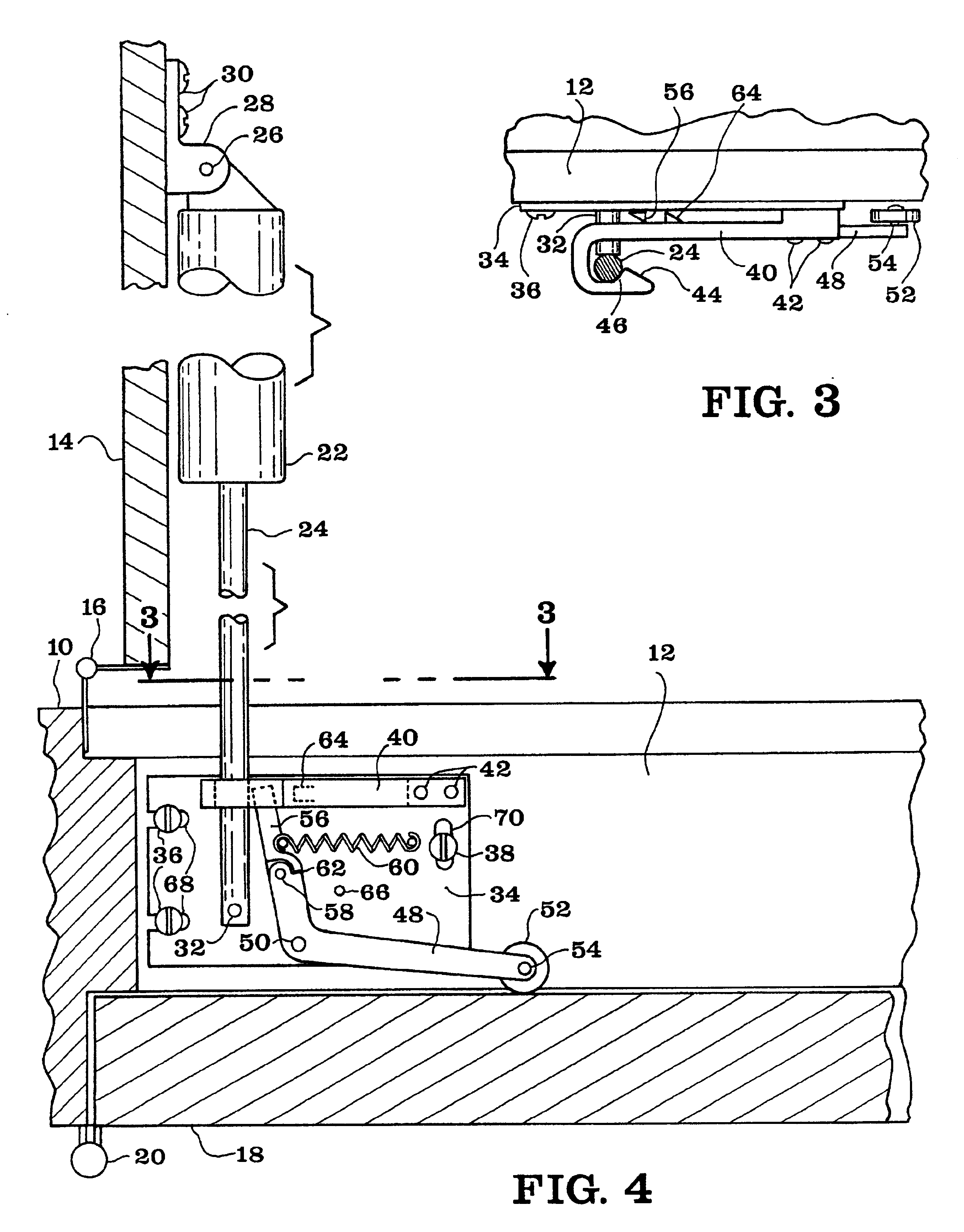
[0028]As required, detailed embodiments of the present invention are disclosed herein; however, it is to be understood that the disclosed embodiments are merely exemplary of the invention that may be embodied in various forms. The figures are not necessary to scale, some features may be exaggerated to show details of particular components. Therefore, specific structural and functional details disclosed herein are not to be interpreted as limiting, but merely as a basis for the claims and as a representative basis for teaching one skilled in the art to variously employ the present invention.

[0029]Referring to FIGS. 1-4, a portion of a conventional doorway is shown including a portion of the hinge-side door jamb 10, an adjacent portion of the lintel 12, a portion of an outer door 14, which could be a screen door or a storm door, an outer door hinge 16, a portion of an inner door 18, which would typically be the main door, and an inner door hinge 20.

[0030]A conventional door closer is ...


PUM


Abstract

A door hold open and controlled release mechanism is designed for usage in a doorway system having an inner door, an outer door and a door closer. It includes a catch mechanism and a catch release mechanism. The catch mechanism holds the outer door, typically a screen door or storm door, in an open position against the closing tendency of the door closer. Movement of the inner door to an open position then toward a closed position triggers the catch release mechanism which allows the outer door to close under the urging of the door closer.

Description

BACKGROUND OF THE INVENTION[0001]1. Field of the Invention[0002]This invention relates to a door closer mechanism adapted for usage in conjunction with a first door mounted in juxtaposition with a second door such as a screen door mounted with an entry door of an edifice or house. More specifically, the present invention relates to a door hold open and controlled release mechanism for use with a two-door arrangement, the mechanism comprising a catch mechanism for holding the first door open and a catch release mechanism for closing the first door upon the closing of the second door.[0003]2. Description of the Related Art[0004]Door closers sold for use with screen doors or storm doors are typically in the form of a cylinder with an axially extendable rod, which is biased toward retracting by an internal coil spring and damped pneumatically or hydraulically. In order to hold the door in an open position a manual latching feature is generally provided in the form of a tab through which...

Claims


Application Information

Patent Timeline
IPC IPC(8): E05F17/00E05F5/00E05F5/12
CPCE05F5/12E05F17/002Y10T16/27E05Y2900/136E05F2017/008
Inventor CRAWFORD, ALAN
Owner CRAWFORD ALAN
Why Eureka
Try Eureka