
Storm brace assembly

a brace assembly and storm technology, applied in hurricane shutters, hurricane shutters/movable grilles, building repairs, etc., can solve the problems of not being able to disclose a brace assembly in the patents, time-consuming to secure and remove plywood over doors, permanent damage to buildings, etc., to prevent undue property damage and facilitate the rotation of thread rods.

Inactive Publication Date: 2005-06-28
WHITWORTH BRECK
View PDF23 Cites 29 Cited by
  • Summary
  • Abstract
  • Description
  • Claims
  • Application Information

AI Technical Summary

Benefits of technology

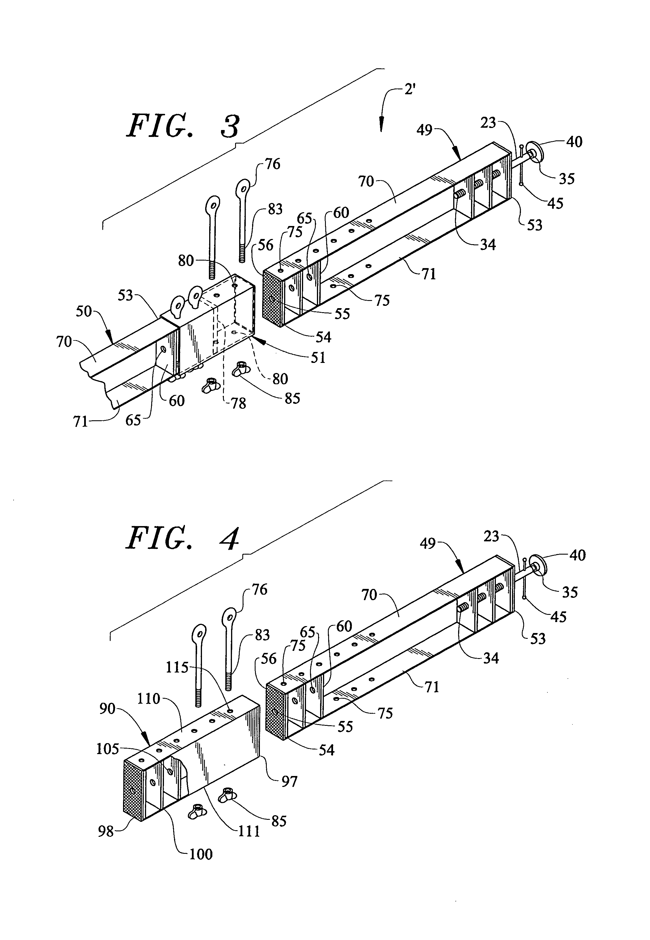
"The present invention is a method and apparatus for holding a panel across a windowed building component to prevent damage during a severe storm. A brace assembly is used, consisting of a bar and a threaded rod, which is fastened to the bar and includes a foot plate. The brace assembly is placed in front of the panel and the threaded rod is rotated to force the foot plate against the frame walls, holding the panel in place. The brace assembly can be used with different types of windowed building components and can be adapted for larger panels by using multiple brace assemblies joined by a connecting strip. The technical effect of the invention is to provide a simple and effective way to protect windowed building components during severe weather events."

Problems solved by technology

The panels are typically attached to the area surrounding the windows or doors with nails or screws, thereby permanently damaging the building.
In addition, it is very time consuming to secure and later remove plywood over doors and windows using traditional methods involving nails or screws.
However, none of these patents discloses a brace assembly for securing a panel across a window, glass door, or the like, wherein the brace assembly that can be quickly installed and may be easily used for a variety of different sized windows and doors.

Method used


Image

  • Storm brace assembly
  • Storm brace assembly
  • Storm brace assembly

Examples


Embodiment Construction

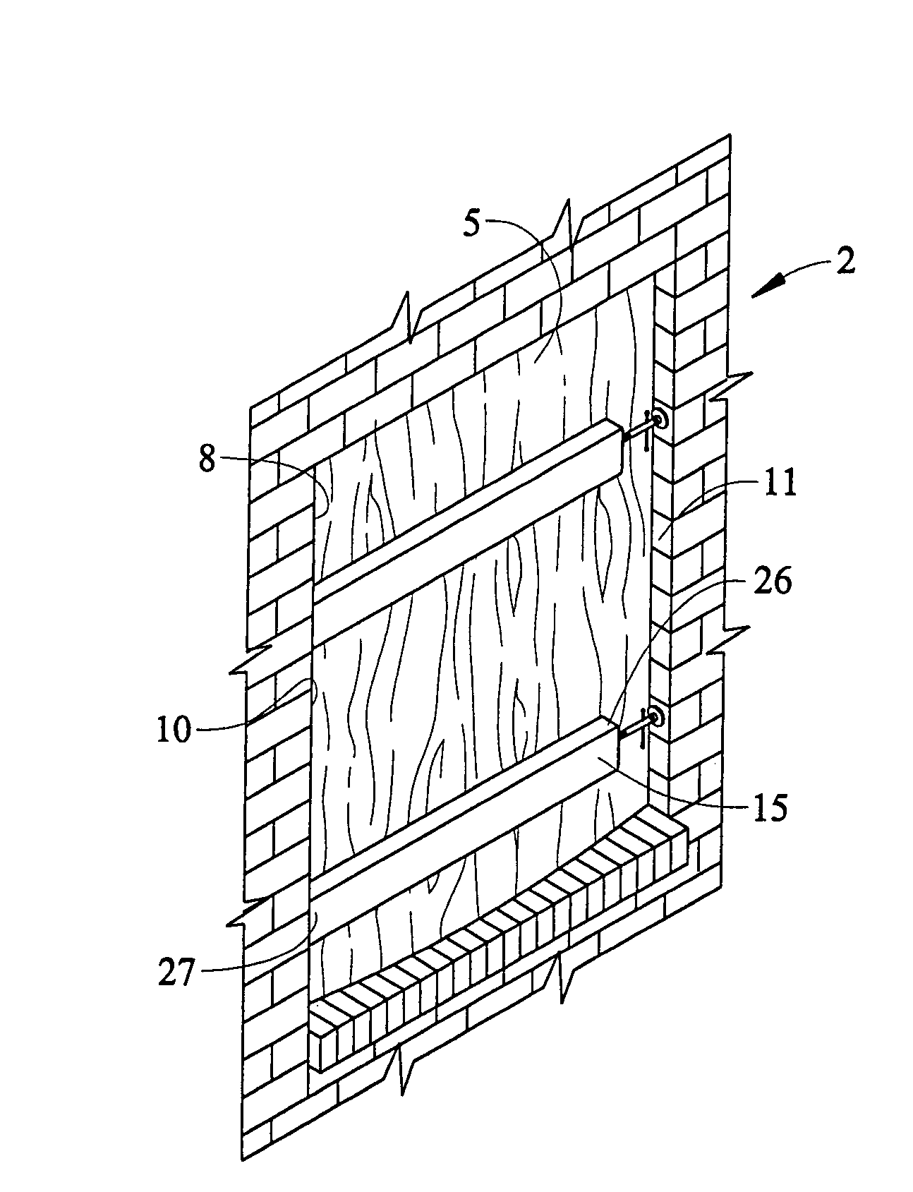
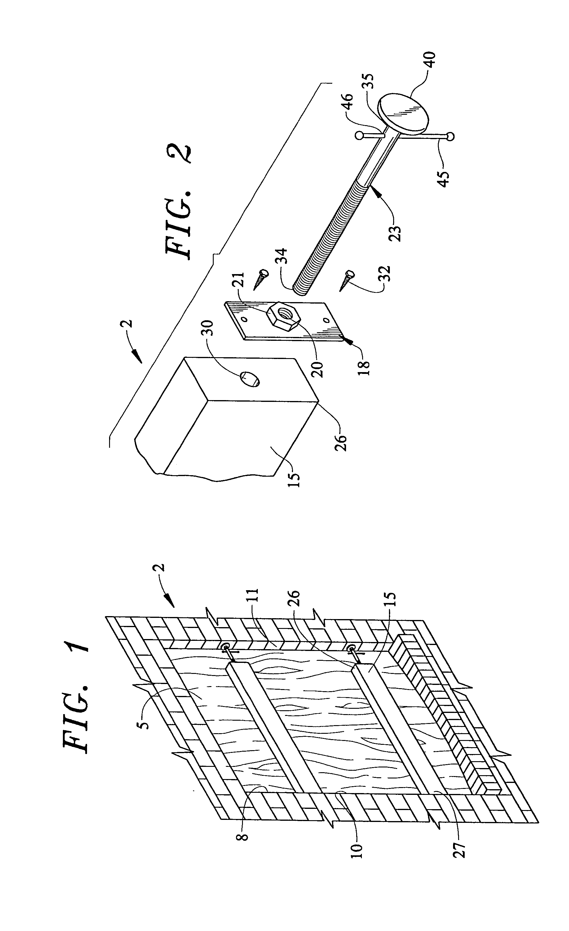
[0015]With initial reference to FIG. 1, a brace assembly constructed in accordance with the present invention is generally indicated at 2. In general, brace assembly 2 is used to retain a protective panel 5, such as a sheet of plywood, within a window or other building opening 8, defined by opposing frame walls 10 and 11, in preparation for a severe storm. In accordance with a first embodiment of the invention as shown in FIGS. 1 and 2, brace assembly2 includes a bar 15, a metal end plate 18 having a threaded hole 20 defined by an integrated nut member 21, and a threaded rod 23. Bar 15, which may be formed of wood, plastic, metal, fiberglass, or the like, has a first end portion 26 and a second end portion 27. In general, bar 15 has a length such that, when placed horizontally between opposing frame walls 10 and 11 of opening 8, enough space is left as to allow for side to side movement of bar 15 as discussed further below. First end portion 26 of bar 15 includes a bore 30 which is ...


PUM


Abstract

A brace assembly is provided to hold a panel against a windowed building component to prevent property damage during a severe storm. The brace assembly includes a bar having a first end portion and a second end portion, wherein the first end portion includes a plate having a threaded hole therein. The brace assembly further includes a threaded rod that is fastened to the threaded hole at one end and includes a foot plate at a second end. A turn handle extends through the threaded rod for facilitating rotation of the threaded rod. When the brace assembly is placed against a panel extending across a windowed building component, rotation of the threaded rod forces the foot plate and bar against opposing frame walls, thereby holding the panel in place.

Description

BACKGROUND OF THE INVENTION[0001]1. Field of the Invention[0002]The present invention pertains to a method and apparatus for protecting windows, glass doors, and the like from damage during severe storms, such as hurricanes.[0003]2. Discussion of the Prior Art[0004]Large panels of plywood or similar rigid materials have long been used to protect windows and glass doors from damage resulting from severe storms, such as hurricanes. The panels are typically attached to the area surrounding the windows or doors with nails or screws, thereby permanently damaging the building. In addition, it is very time consuming to secure and later remove plywood over doors and windows using traditional methods involving nails or screws.[0005]In attempts to solve problems associated with securing buildings for an imminent storm, some devices have been developed to secure plywood panels without damaging the surrounding building structure. For example, U.S. Pat. Nos. 5,673,883, 6,330,768 and 6,371,422 al...

Claims


Application Information

Patent Timeline
Patent Type & Authority Patents(United States)
IPC IPC(8): E06B9/02
CPCE06B9/02E06B2009/005
Inventor WHITWORTH, BRECK
Owner WHITWORTH BRECK
Learn More