
Temperature control apparatus and method of operating the same

a technology of temperature control apparatus and temperature control unit, which is applied in the direction of domestic cooling apparatus, lighting and heating apparatus, refrigeration components, etc., can solve the problem of reducing the efficiency of the temperature control unit during operation, and achieve the effect of reducing the efficiency of the temperature control uni

Inactive Publication Date: 2005-06-28
THERMO KING CORP
View PDF73 Cites 30 Cited by
  • Summary
  • Abstract
  • Description
  • Claims
  • Application Information

AI Technical Summary

Benefits of technology

The present invention provides a temperature control unit with a refrigeration circuit that can efficiently control the temperature during heating and defrost modes. The unit includes a valve that can direct the refrigerant either through a first flow path or a second flow path, which bypasses a portion of the refrigeration circuit. This valve can be moved to optimize the efficiency of the refrigeration circuit during different modes of operation. The invention also provides methods for measuring the temperature and initiating a recovery cycle when the temperature change is outside the efficiency range. The technical effects of the invention include improved control of temperature, reduced energy consumption, and improved efficiency of the refrigeration circuit.

Problems solved by technology

This accumulation of refrigerant in the condenser and in other elements of the temperature control unit that are not connected to the heating circuit reduces the efficiency of the temperature control unit during operation in the heating and defrost modes.

Method used


Image

  • Temperature control apparatus and method of operating the same
  • Temperature control apparatus and method of operating the same
  • Temperature control apparatus and method of operating the same

Examples


Embodiment Construction

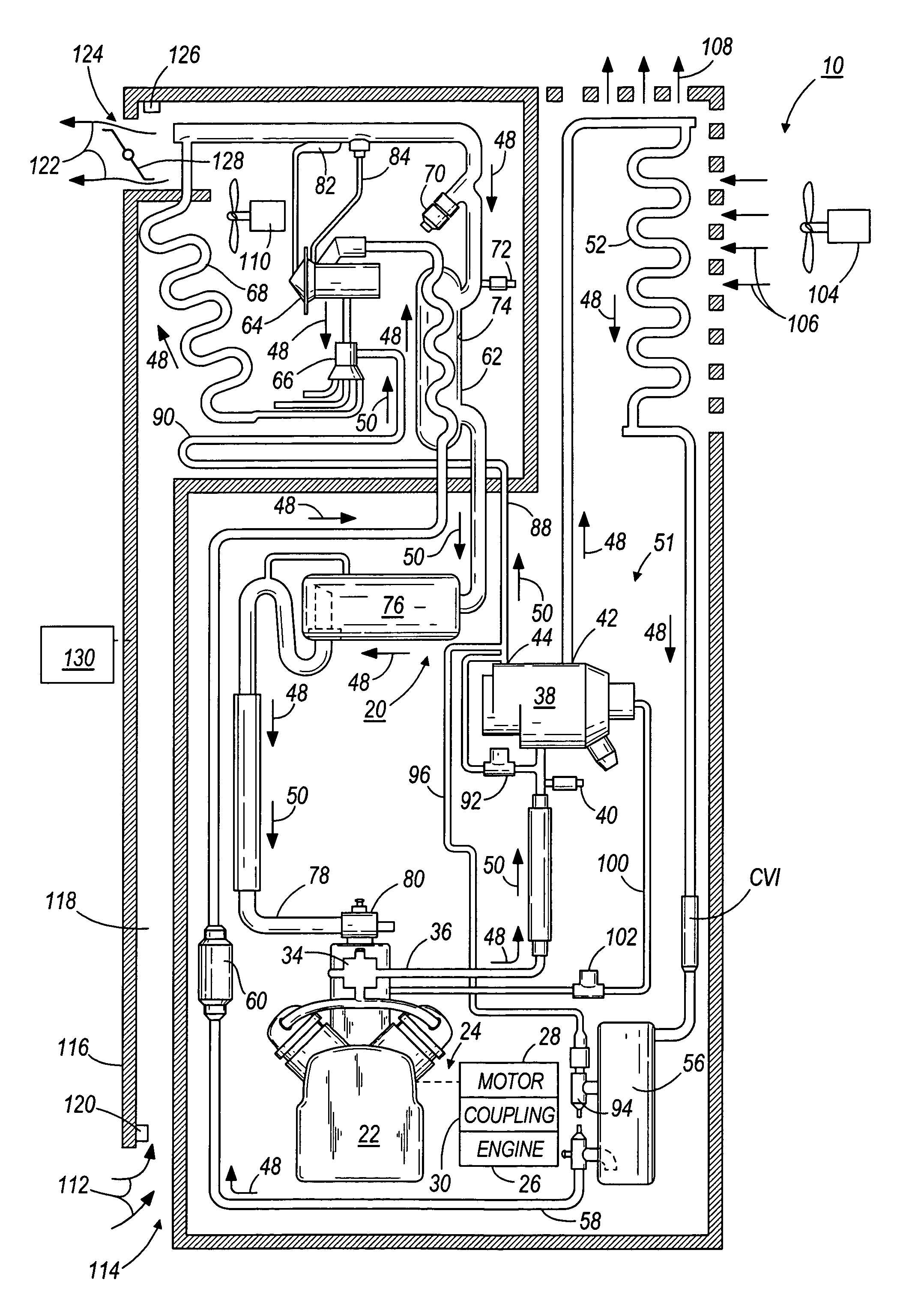
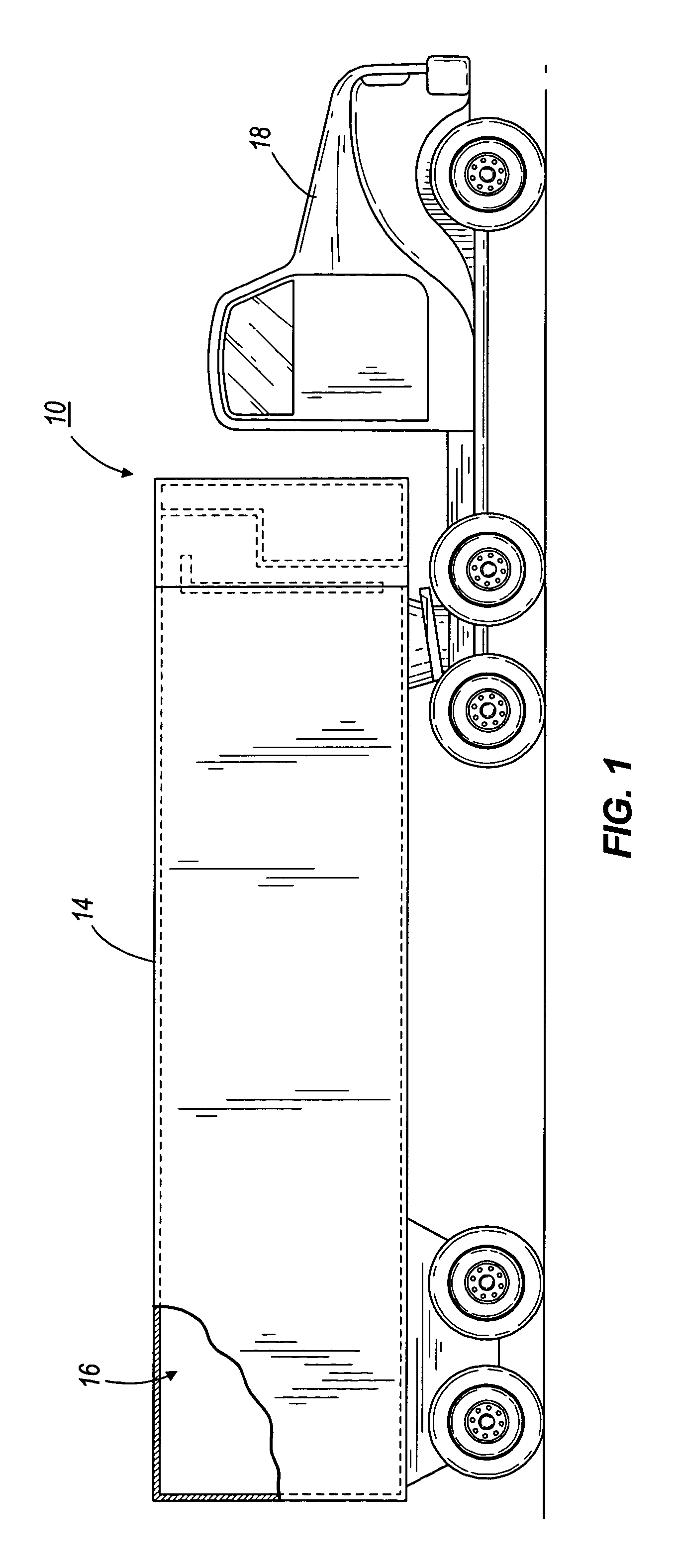
[0018]FIG. 1 illustrates a temperature control unit 10 in accordance with the present invention. The temperature control unit 10 is especially suitable for use in transport applications and can be mounted on a container, truck, or trailer. FIG. 1 shows the temperature control unit 10 mounted on a trailer 14 having a load space 16. The trailer 14 is pulled by a tractor 18, as is understood by those skilled in the art. In other constructions (not shown), the temperature control unit 10 can be mounted on a storage container or another vehicle, such as, for example, a tractor-trailer combination.

[0019]As used herein and in the claims, the term “load space” includes any space to be temperature and / or humidity controlled, including transport and stationary applications for the preservation of food, beverages, plants, flowers, and other perishables and maintenance of a proper atmosphere for the shipment of industrial products. Also, as used herein and in the claims, the term “refrigerant” ...


PUM


Abstract

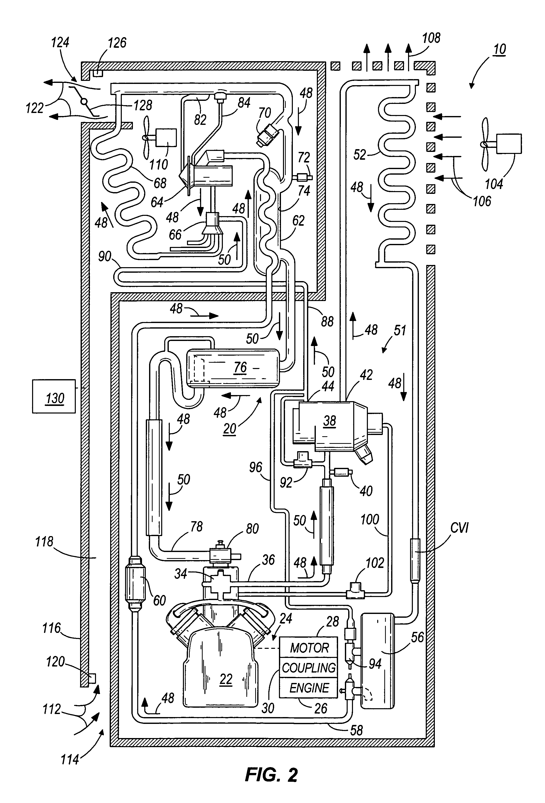
A temperature control unit and a method of operating a temperature control unit. The temperature control unit including a refrigeration circuit enclosing a refrigerant and having a compressor, a condenser, and an evaporator coil. The method including providing a first flow path extending through the compressor, the condenser, and the evaporator, providing a second flow path extending through the compressor and the evaporator, the second flow path bypassing a section of the refrigeration circuit, directing refrigerant through the first flow path during operation in a cooling mode, directing refrigerant through the second flow path during operation in a heating mode, and recovering refrigerant from the section of the refrigeration circuit during operation in a recovery cycle.

Description

FIELD OF THE INVENTION[0001]The invention relates to a temperature control apparatus, and more particularly to transport temperature control apparatuses and a method of operating the same.BACKGROUND OF THE INVENTION[0002]Trucks and tractor-trailer combinations frequently transport cargo that must be maintained at a predetermined temperature during transportation. Vehicles that transport temperature sensitive cargo typically have one or more load spaces that are maintained at a set point temperature by a temperature control unit, having a compressor, a condenser, a flow control valve, an expansion valve, and an evaporator coil. Operation of the temperature control unit is generally controlled and monitored by an electronic controller.[0003]Generally, temperature control units operate in cooling and heating modes, depending, at least in part, upon the temperature of the load space and the ambient temperature outside the air-conditioned space. When the temperature of the load space is ...

Claims


Application Information

Patent Timeline
Patent Type & Authority Patents(United States)
IPC IPC(8): B60H1/00F25B49/02F25B41/04F25D11/00F25B47/02F25B27/00F25B40/00B60P3/20B60H1/32F25D29/00
CPCB60H1/00914F25B41/04F25B49/02B60H1/3213F25D11/003F25B27/00F25B40/00F25B47/022F25B2327/001F25B2400/0403F25B2400/0411F25B2400/16F25B2400/19F25B2700/21172F25B2700/21173B60H2001/00961F25B41/20
Inventor SRICHAI, PANAYA ROBERTMOHS, WILLIAM FRANCISLUDWIG, BRADLEY MICHAEL
Owner THERMO KING CORP
Learn More