Viscometer

a technology of viscometer and excitation current, which is applied in the direction of direct mass flowmeter, liquid/fluent solid measurement, instruments, etc., can solve the problems of inability to convey to the user, gas bubbles in the fluid may be trapped, and the viscosity value determined by means of excitation current may exhibit considerable inaccuracy

Inactive Publication Date: 2005-06-28
ENDRESS HAUSER FLOWTEC AG
View PDF4 Cites 108 Cited by
  • Summary
  • Abstract
  • Description
  • Claims
  • Application Information

AI Technical Summary

Benefits of technology

[0063]A further advantage of the invention therefore consists in the fact that it can also be implemented in commercially available Coriolis mass flowmeter-densimeters, for example, and virtually independently of the concrete shape and number of flow tubes used in the respective transducer, i.e., without any basic change in the mechanical design of the transducer.
therefore consists in the fact that it can also be implemented in commercially available Coriolis mass flowmeter-densimeters, for example, and virtually independently of the concrete shape and number of flow tubes used in the respective transducer, i.e., without any basic change in the mechanical design of the transducer.

Problems solved by technology

It has turned out, however, that in spite of viscosity and density being maintained virtually constant, particularly under laboratory conditions, the viscosity value determined by means of the excitation current may exhibit considerable inaccuracies, which may amount to as much as one hundred times the actual viscosity of the fluid.
In U.S. Pat. No. 4,524,610, a possible cause of this problem is indicated, namely the fact that gas bubbles in the fluid may be trapped at the wall of the flow tube.
This, however, is a very specific solution which is only conditionally realizable, particularly in industrial process measurement technology.
On the one hand, the pipe into which the transducer is to be inserted would have to be adapted to the latter and not vice versa, which probably cannot be conveyed to the user.
On the other hand, the flow tubes may also have a curved shape, so that the problem cannot be solved by adapting the position of installation.
It has also turned out that the aforementioned inaccuracies of the measured viscosity value cannot be appreciably reduced even if a vertically installed, straight flow tube is used.
Variations in the measured viscosity value of a moving fluid cannot be prevented in this manner, either.

Method used


Image

  • Viscometer
  • Viscometer
  • Viscometer

Examples


Embodiment Construction

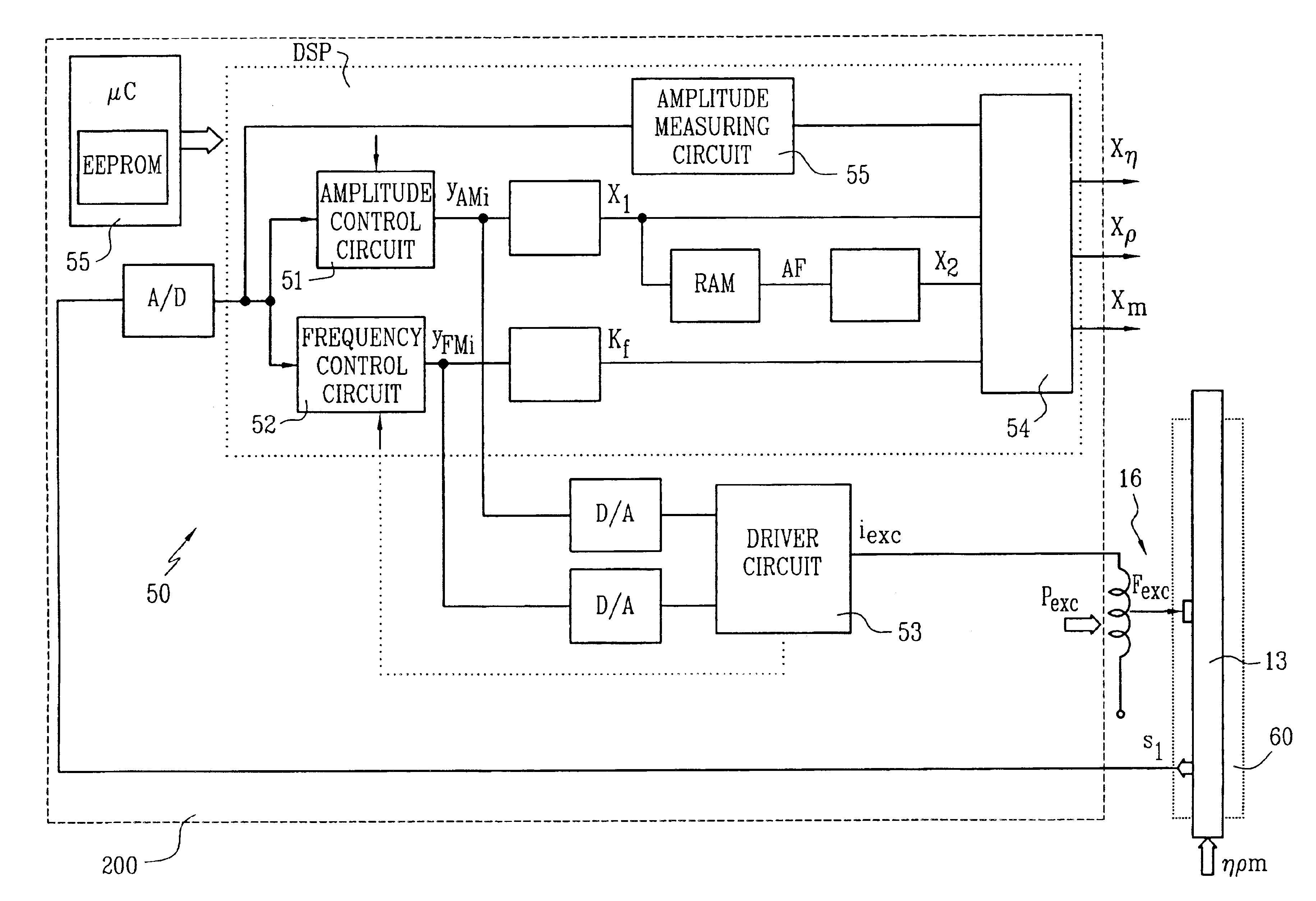
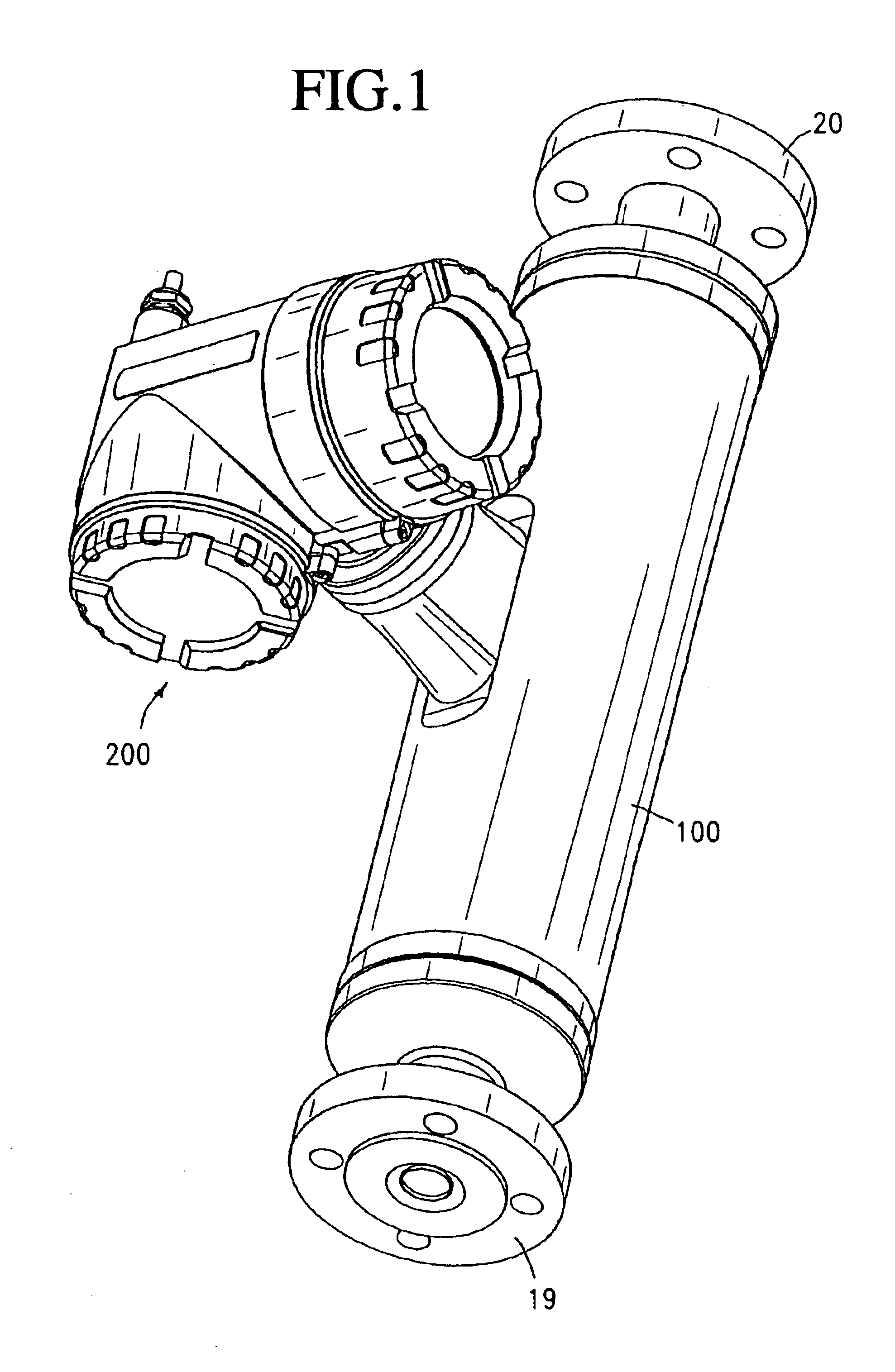
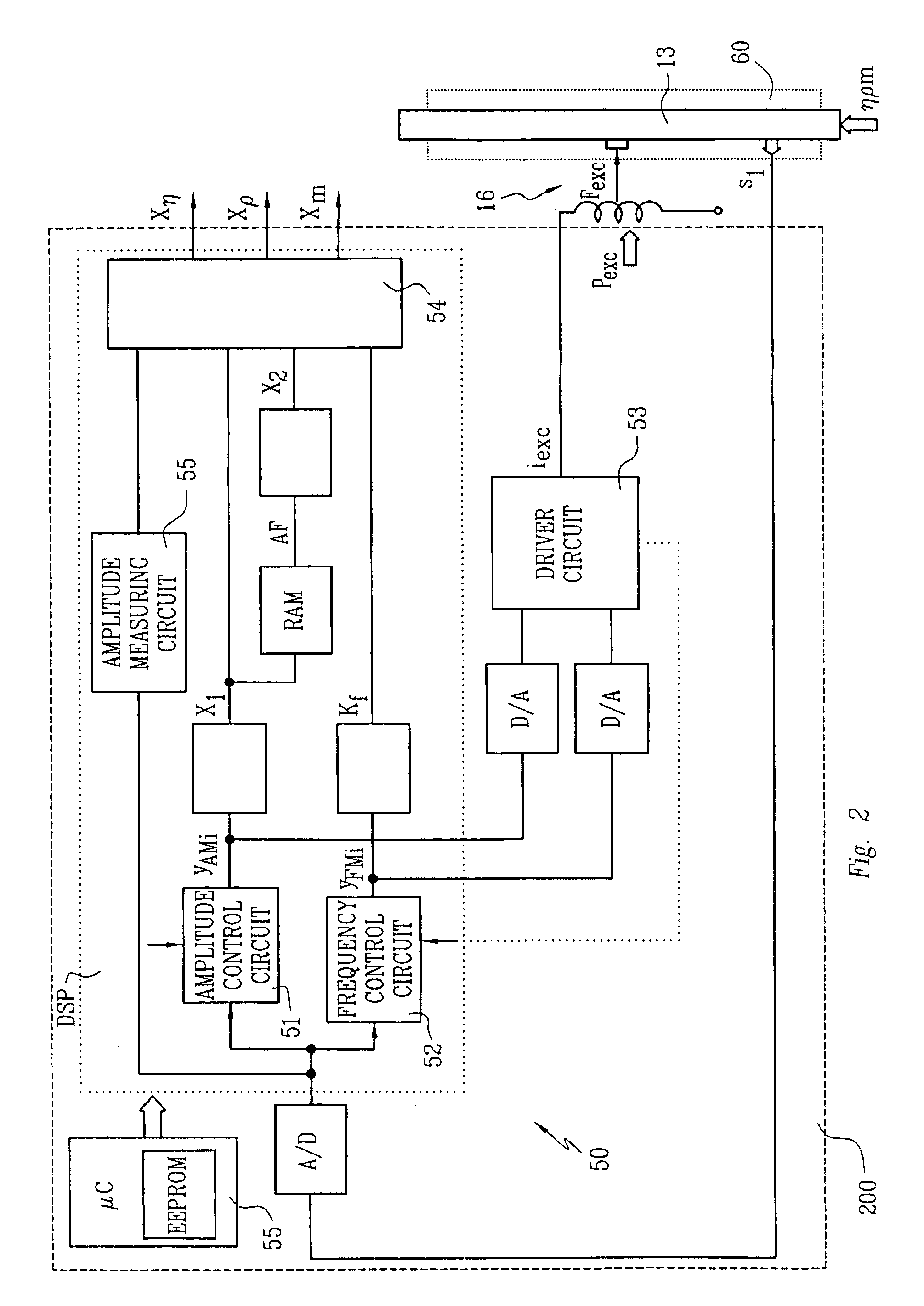
[0071]FIG. 1 shows schematically a viscometer with a vibratory transducer 10, preferably housed in a transducer case 100, and with meter electronics 50, housed in an electronics case 200 and, as shown in FIG. 2, electrically connected to transducer 10. The viscometer serves in particular to sense a viscosity, η, of a fluid flowing in a pipe (not shown) and to map this viscosity into a measured viscosity value Xη representing this viscosity η. By means of transducer 10, which is driven by meter electronics 50, friction forces are generated in the fluid passing therethrough which are dependent on the viscosity η and react on transducer 10 in a measurable manner, i.e., which can be detected using sensor technology and converted into useful input signals for subsequent evaluation electronics.

[0072]In the preferred case where the viscometer is designed to be coupled to a field bus, the, preferably programmable, meter electronics 50 will include a suitable communication interface for data...


PUM

PropertyMeasurementUnit
resonance frequencyaaaaaaaaaa
viscosityaaaaaaaaaa
internal friction forcesaaaaaaaaaa

Abstract

The viscometer provides a viscosity value (Xη) which represents the viscosity of a fluid flowing in a pipe connected thereto. It comprises a vibratory transducer with at least one flow tube for conducting the fluid, which communicates with the pipe. Driven by an excitation assembly, the flow tube is vibrated so that friction forces are produced in the fluid. The viscometer further includes meter electronics which feed an excitation current (iexc) into the excitation assembly. By means of the meter electronics, a first internal intermediate value (X1) is formed, which corresponds with the excitation current (iexc) and thus represents the friction forces acting in the fluid. According to the invention, a second internal intermediate value (X2), representing inhomogeneities in the fluid, is generated in the meter electronics, which then determine the viscosity value (Xη) using the two intermediate values (X1, X2). The first internal intermediate value (X1) is preferably normalized by means of an amplitude control signal (yAM) for the excitation current (iexc), the amplitude control signal corresponding with the vibrations of the flow tube. As a result, the viscosity value (Xη) provided by the viscometer is highly accurate and robust, particularly independently of the position of installation of the flow tube.

Description

CROSS-REFERENCE TO RELATED APPLICATION[0001]This application claims the benefit of the filing of Provisional Application No. 60 / 322,743, filed Sep. 18, 2001.BACKGROUND OF THE INVENTION[0002]1. Field of the Invention[0003]This invention relates to a viscometer for a fluid flowing in a pipe and to a method of determining the viscosity of the fluid.[0004]2. Discussion of the Prior Art[0005]In measurement and automation technology, the viscosity of a fluid flowing in a pipe, particularly of a liquid, is frequently determined by means of meters which, using a vibratory transducer and meter electronics connected thereto, induce internal friction forces in the fluid and derive therefrom a measurement signal representative of the respective viscosity.[0006]Such viscometers are described, for example, in U.S. Pat. No. 4,524,610 in published International Application, WO-A 95 / 16897 and comprise:[0007]a vibratory transducer[0008]with an essentially straight flow tube for conducting the fluid, ...

Claims


Application Information

Patent Timeline
Patent Type & Authority Patents(United States)
IPC IPC(8): G01N11/10G01N11/16
CPCG01F1/8413G01F1/8418G01F1/8422G01F1/8427G01F1/849G01N11/16G01N11/162G01N11/167G01F1/8431G01N2009/006G01F1/8468G01N9/002
Inventor DRAHM, WOLFGANGRIEDER, ALFRED
Owner ENDRESS HAUSER FLOWTEC AG
Why Eureka
Try Eureka