Directly controlled fuel injector with pilot plus main injection sequence capability

a fuel injector and pilot technology, applied in the direction of liquid fuel feeders, electric control, machines/engines, etc., can solve the problems of inconsistent injection of fuel, inability to consistently and accurately control the relatively small pilot injection, and inability to achieve the goal of lowering undesirable engine emissions. consistent and accurate pilot injection, fuel pressure reduction

Inactive Publication Date: 2005-06-28
CATERPILLAR INC
View PDF10 Cites 34 Cited by
  • Summary
  • Abstract
  • Description
  • Claims
  • Application Information

AI Technical Summary

Benefits of technology

[0006]In one aspect, a method of injecting fuel includes a step of raising fuel pressure in a fuel injector at least in part with a pressure control valve. A nozzle valve is opened for a pilot injection after fuel pressure is above a valve opening pressure for the nozzle valve. This is accomplished at least in part by actuating a needle control valve in a first direction. The nozzle valve is then closed while fuel pressure is maintained above the valve opening pressure, at least in part by actuating the needle control valve in a second direction. Next, the nozzle valve is reopened for a main injection while fuel pressure is maintained above the valve opening pressure, at least in part by actuating the needle control valve back in its first direction. Finally, fuel pressure in the fuel injector is reduced.
[0007]In another aspect, a method of improving accuracy of a pilot injection in a pilot plus main injection sequence includes a step of holding the nozzle valve closed while fuel pressure surpasses a valve opening pressure for the nozzle valve. The nozzle valve is then opened at least in part by either energizing or deenergizing an electrical actuator. The nozzle valve is enclosed to end the pilot injection event at least in part by the other of energizing and de-energizing the electrical actuator.

Problems solved by technology

While it may be known that pilot plus main injection sequences are desirable at certain engine operating conditions, it has proven problematic to consistently and accurately control the relatively small pilot injection.
Not only do realistic geometrical tolerances and other factors cause a plurality of otherwise identical fuel injectors to behave somewhat differently when supplied with identical control signals, a given injector may also not produce consistent injection results based upon receiving identical control signals over a plurality of engine cycles.
If the injector's behavior deviates too substantially from an expected injection sequence, the goal of lower undesirable emissions from the engine may not be consistently achieved.

Method used


Image

  • Directly controlled fuel injector with pilot plus main injection sequence capability
  • Directly controlled fuel injector with pilot plus main injection sequence capability
  • Directly controlled fuel injector with pilot plus main injection sequence capability

Examples


Embodiment Construction

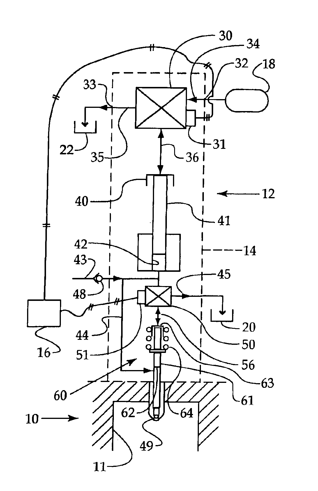
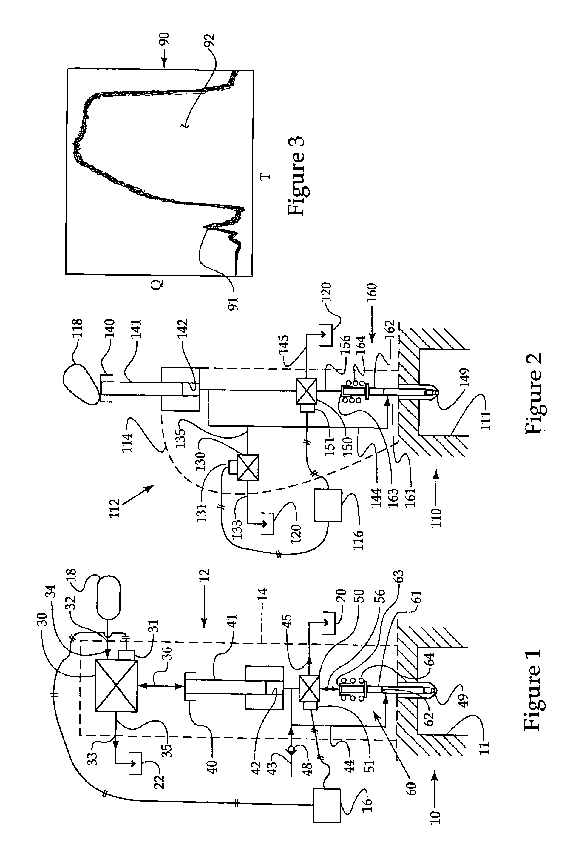
[0012]Referring to FIGS. 1 and 2, example fuel injection systems 12 and 112 are illustrated in a schematic form. Fuel injection system 12 is a hydraulically actuated pressure intensified fuel injector that includes a direct control needle valve 60. Fuel injection system 112 is a mechanically actuated fuel injector that also includes a direct control needle valve 160. Both fuel injection systems include a separate pressure control valve. Thus, during each engine cycle, each fuel injector will cycle between high and low pressure states during and between injection sequences, respectively. Thus, the present disclosure is applicable to any fuel injection system that cycles between high and low pressure, and includes an electrical actuator associated with a direct control needle valve. Apart from the fuel injection systems illustrated, the present disclosure might also find potential application to common rail fuel injectors that are equipped with both an admission valve (pressure contro...


PUM


Abstract

In one class of fuel injection systems, the individual fuel injectors cycle between high and low pressure during and between injection sequences in a given engine cycle. The fuel injectors may be hydraulically actuated, mechanically actuated, and possibly include common rail injectors equipped with an admission valve that enable the fuel injectors to cycle between high and low pressures. Many of these fuel injection systems also include a directly controlled nozzle valve that can apply or relieve pressure on a closing hydraulic surface associated with the nozzle valve. The nozzle valve is typically spring-biased and therefore has a pre-defined valve opening pressure that defines at what fuel pressure the nozzle valve will open when pressure is relieved on its closing hydraulic surface. While these fuel injection systems can produce a wide variety of rate shapes and injection sequences, generally, an injection sequence of particular interest is one that includes a relatively small volume pilot injection followed quickly in time by a relatively large volume main injection. In order to make the accuracy of the pilot injection more consistent, the nozzle valve is held closed while fuel pressure in the fuel injector builds and surpasses the valve opening pressure of the nozzle valve. This strategy helps to alleviate sensitivity of the pilot injection volume to inherent variability factors, such as geometrical tolerances, within and between fuel injectors.

Description

RELATION TO OTHER PATENT APPLICATION[0001]This application is a continuation in part of co-pending patent application Ser. No. 10 / 637,452, filed Aug. 8, 2003, entitled Hydraulic Fuel Injection System With Independently Operable Direct Control Needle Valve.TECHNICAL FIELD[0002]The present disclosure relates generally to pilot plus main fuel injection sequences, and more particularly to a strategy for improving accuracy in a pilot injection for fuel injectors that cycle between high and low pressure during each engine cycle.BACKGROUND[0003]Over the years, engineers have come to recognize that some undesirable emissions can be substantially reduced using particular injection sequences and / or rate shapes at particular engine operating conditions. For instance, engineers have come to recognize that at some engine operating conditions, it is desirable to deliver fuel to the engine cylinder in a so called pilot plus main injection sequence. By injecting a relatively small pilot amount of f...

Claims


Application Information

Patent Timeline
Patent Type & Authority Patents(United States)
IPC IPC(8): F02M57/00F02M57/02F02M45/08F02M47/02F02M45/00F02D41/20F02D41/40
CPCF02M57/023F02M57/025F02M47/027F02M45/08F02D41/2096F02D41/403
Inventor SUN, JINHUISTOCKNER, ALAN R.
Owner CATERPILLAR INC
Why Eureka
Try Eureka