Strip casting apparatus

a casting apparatus and strip technology, applied in the field of metal strip casting, can solve the problems of high local heat loss rate, exacerbate the problem of strip defects, and generalized “snake eggs” defects, and achieve the effect of inhibiting the formation of skulls

Inactive Publication Date: 2005-06-28
NUCOR CORP
View PDF15 Cites 7 Cited by
  • Summary
  • Abstract
  • Description
  • Claims
  • Application Information

AI Technical Summary

Benefits of technology

[0006]Although triple point pouring has been effective to reduce the formation of skulls in the triple point regions of the casting pool, it has not been possible completely to eliminate the problem. The generation of skulls and resulting strip defects has been found to be remarkably sensitive to even minor variations in the flow of metal into the triple point regions of the casting pool. Even minor changes in the distance between the nozzle ends (where the nearest nozzle openings are located) and the confining plates due to thermal expansion and / or wear has been found to be sufficient to cause defects in the strip. As the distances between the nozzle ends and the confining plates are reduced the downwardly inclined flow of metal from the triple point pouring passages in the ends of the nozzle impinges higher on the confining plates. This change can lead to the formation of skulls in the casting pool and subsequent snake egg defects in the strip. In extreme cases, changes in these distances can cause the poured molten metal to surge upwardly between the nozzle ends and confining plates, and spill over the upper edges of the confining plates.
[0013]nozzle end shifters to shift the nozzle pieces having outer nozzle ends nearest the confining plates on the nozzle supports with inward movements matching the inward movements of said confining plates accommodating wear of the confining plates to maintain substantially constant spacings between the confining plates and the nearest nozzle ends.
[0021]nozzle end shifters to shift the nozzle pieces defining the outer nozzle ends of the delivery nozzle with inward movements matching the inward movements of said side plates accommodating wear of the side plates to maintain substantially constant spacings between the side plates and the nozzle ends, wherein the nozzle end shifters comprise a pair of moveable structures disposed one at each end of the casting roll assembly, drives to move the moveable structures longitudinally of the rolls, nozzle attachments to attach the moveable structures to the two nozzle pieces defining the outer nozzle ends nearest the confining plates so that those two nozzle pieces are moved with the movable structures, and controls responsive to inward advances of the confining plates along the casting rolls to cause the drives to move the moveable structures inwardly and shift said two nozzle pieces with inward movements matching inward movement of the confining plates.
[0037]The nozzle pieces are moved by the nozzle drives with or along the nozzle supports depending on the embodiment. In either event, the delivery nozzle drives may vary the distance between the confining plates and the outer nozzle ends nearest the confining plates to maintain appropriate flow of molten metal into the triple point region while allowing for thermal expansion and wear of the nozzle pieces and confining plates and inhibit formation of skulls in the casting pool. The apparatus may also comprise an inspector, such as a video camera, to allow an operator to monitor the melt flow in the triple point region and electrical controls actuated by an operator may energize the nozzle drives to move the nozzles pieces relative to the confining plates.
[0044]The method may vary the distance between the confining plates and the outer nozzle ends nearest the confining plates to maintain appropriate flow of molten metal into the triple point region while allowing for thermal expansion and wear of the nozzle pieces and confining plates, and inhibiting formation of skulls in the casting pool. The method may also comprise inspecting the casting pool in the triple point region, as with a video camera, to allow an operator to monitor the melt flow in that region and control movement of the nozzle drives and in turn the nozzles pieces defining the outer nozzle ends relative to the confining plates.

Problems solved by technology

Although, twin roll casting has been applied with some success to non-ferrous metals which solidify rapidly on cooling, there have been problems in applying the technique to the casting of ferrous metals which have high solidification temperatures and tend to produce defects in the cast strip caused by uneven solidification on the casting roll surfaces of the rolls.
One particular problem arises from the formation of pieces of solid metal known as “skulls” in the casting pool in the region of the side confining plates.
These problems are exacerbated when efforts are made to reduce the superheat of the incoming molten metal.
This high rate of local heat loss is reflected in the tendency to form “skulls” of solid metal in this region which can grow to a considerable size and go through the nip between the rolls causing defects in the strip generally known as “snake eggs”.
Variation in this distance may be brought about by inaccurate location of the confining plates or the delivery nozzle during set up, or by subsequent change in the distance due to thermal expansion and wear in the confining plates or the nozzle openings of the delivery nozzles during casting.
This problem remains even if the delivery nozzle is designed specifically to provide an increased flow of metal to the “triple point” regions (i.e., where the confining plates and casting rolls meet at the meniscus regions of the casting pool) and increase the heat input to these regions of the casting pool.
Although triple point pouring has been effective to reduce the formation of skulls in the triple point regions of the casting pool, it has not been possible completely to eliminate the problem.
This change can lead to the formation of skulls in the casting pool and subsequent snake egg defects in the strip.
In extreme cases, changes in these distances can cause the poured molten metal to surge upwardly between the nozzle ends and confining plates, and spill over the upper edges of the confining plates.

Method used


Image

  • Strip casting apparatus
  • Strip casting apparatus
  • Strip casting apparatus

Examples


Embodiment Construction

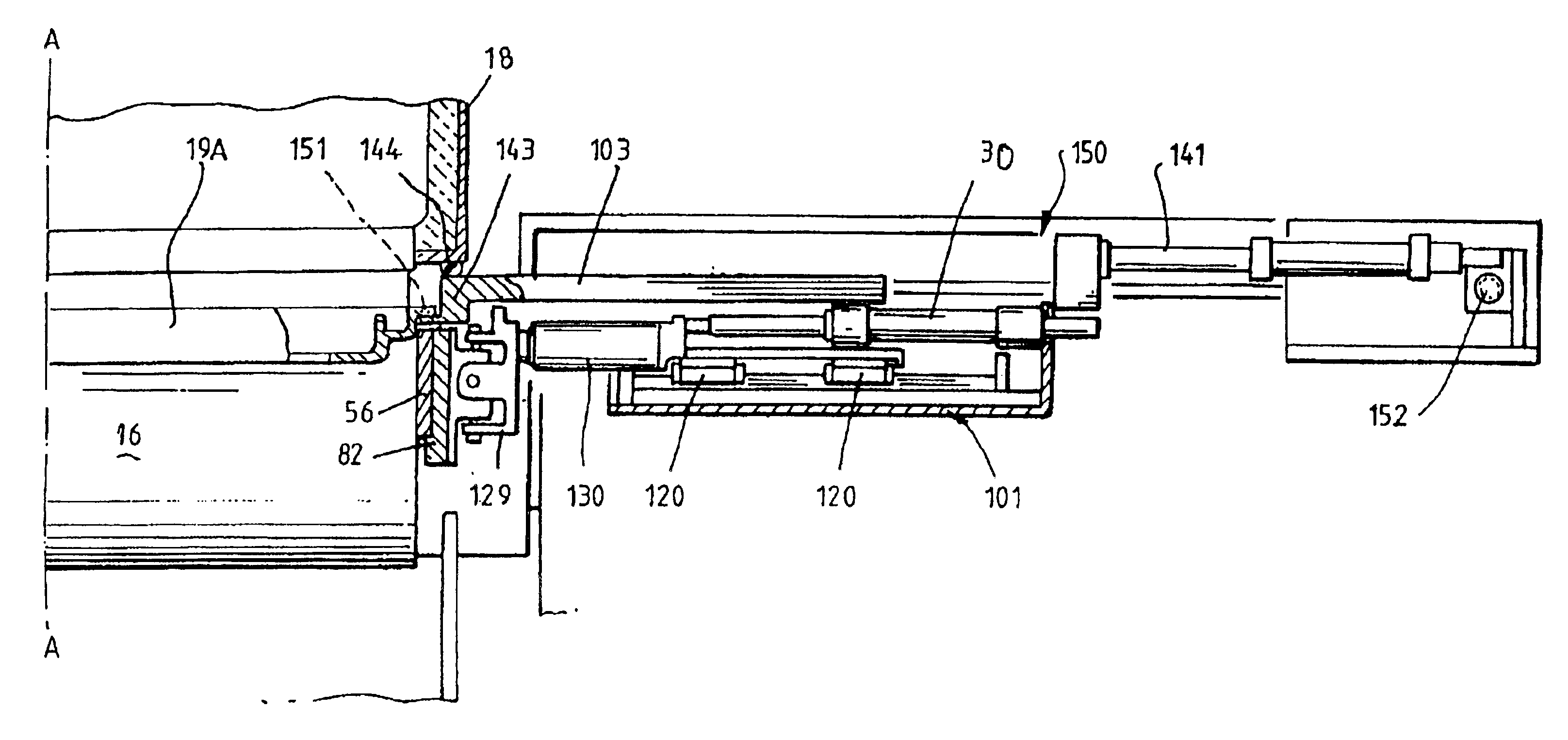
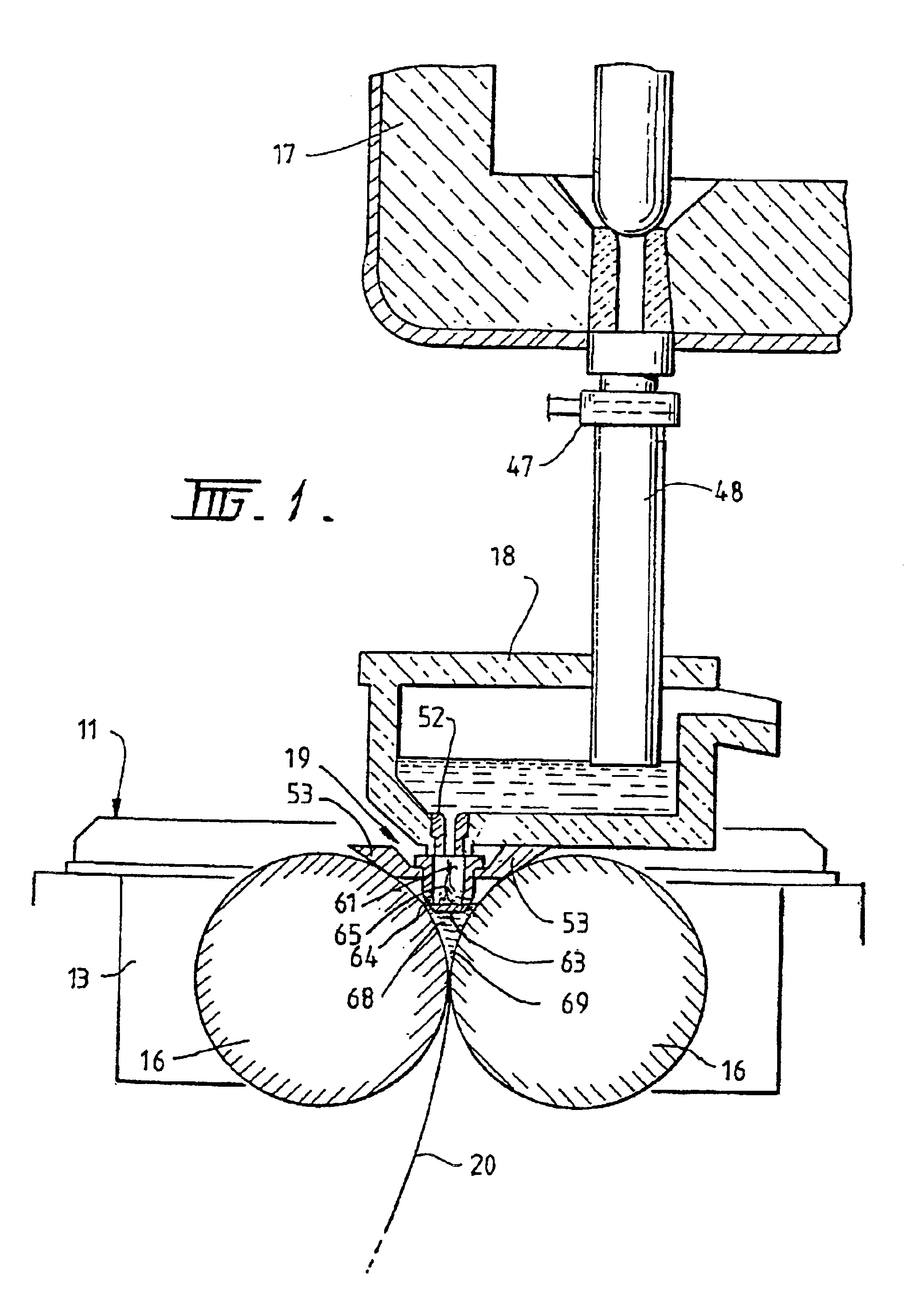
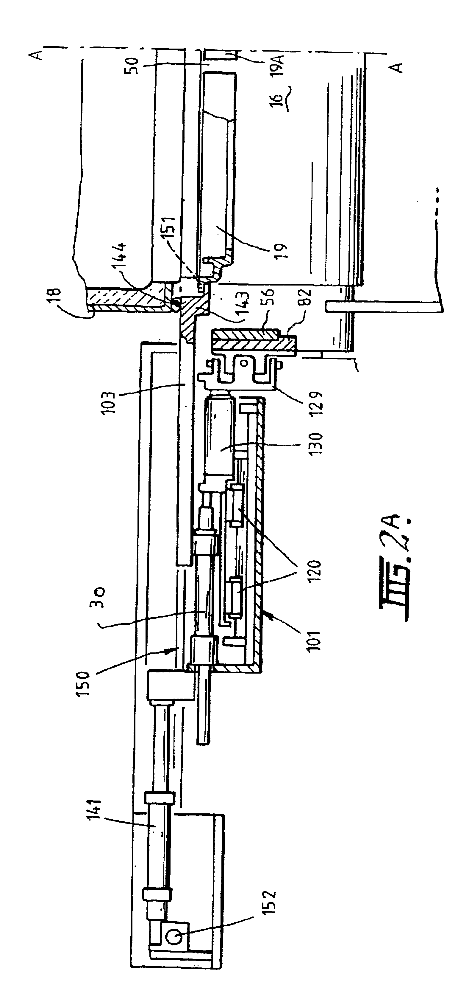
[0057]The illustrated caster comprises a main machine frame 11 which supports a casting roll module in the form of a cassette 13 which can be moved into an operative position in the caster as a unit, and can readily be removed as needed when the casting rolls are to be replaced. Cassette 13 carries a pair of casting rolls 16 arranged generally in parallel to form a nip 69 there between. Molten metal is supplied during a casting operation, a campaign, from a ladle (not shown) via a tundish 17, distributor 18 and delivery nozzle 19 to create a casting pool 68 supported on the casting rolls 16 above the nip. The casting pool 68 is confined at the ends of the nip by a pair of side confining plates 56 as explained below. Casting rolls 16 are water cooled so that melt shells solidify on the moving roll surfaces and are brought together at the nip 69 to produce a solidified strip product 20 extending downwardly from the nip. This product may be cooled and fed to a standard coiler.

[0058]Cas...


PUM

PropertyMeasurementUnit
distanceaaaaaaaaaa
distanceaaaaaaaaaa
distanceaaaaaaaaaa

Abstract

Apparatus and method for casting metal strip by controlling the distance between the confining side plates confining the casting pool and the outer nozzle ends of discrete nozzle pieces of the delivery nozzle delivering the molten melt. The nozzle pieces defining the outer nozzle ends may be moved and control separately from the position of the confining plates, or with the position of the confining plates, by a nozzle delivery drive. The distance between the outer nozzle ends and the confining plates may be set before casting and maintained during casting with wear and thermal expansion of the confining plates, nozzle pieces, or both, or varied during the casting operation, to inhibit the formation of skulls in the casting pool and the formation of “snake eggs” in the cast strip.

Description

RELATED APPLICATIONS[0001]This application is a continuation in part of U.S. patent application Ser. No. 09 / 980,735, filed Oct. 31, 2001, to issue Jul. 8, 2003 as U.S. Pat. No. 6,588,492, and claims priority from Australian provisional patent application Serial No. PQ 0071, filed May 3, 1999.BACKGROUND AND SUMMARY[0002]This invention relates to the casting of metal strip. It has particular but not exclusive application to the casting of ferrous metal strip.[0003]It is known to cast metal strip by continuous casting in a twin roll caster. Molten metal is introduced between a pair of counter-rotated horizontal casting rolls which are cooled so that metal shells solidify on the moving casting roll surfaces and are brought together at the nip between the casting rolls to produce a solidified strip product delivered downwardly from the nip. The term “nip” is used herein to refer to the general region at which the casting rolls are closest together. The molten metal may be poured from a l...

Claims


Application Information

Patent Timeline
Patent Type & Authority Patents(United States)
IPC IPC(8): B22D11/06
CPCB22D11/066B22D11/0642
Inventor FISH, JOHN ANDREWKATO, HEIJI
Owner NUCOR CORP
Why Eureka
Try Eureka