Clutch arrangement

a technology of clumping and lining, which is applied in the direction of mechanical actuated clutches, fluid couplings, couplings, etc., can solve the problems of overheating in the region of friction elements, affecting affecting the flow of fluid in this manner, so as to improve the transmission capacity of torque, improve the transmission efficiency, and improve the effect of fluid-conveying efficiency

Inactive Publication Date: 2005-06-28
ZF FRIEDRICHSHAFEN AG
View PDF19 Cites 21 Cited by
  • Summary
  • Abstract
  • Description
  • Claims
  • Application Information

AI Technical Summary

Benefits of technology

[0008]Since, in the case of the clutch arrangement according to the invention, it is therefore the friction elements themselves which induce a circulation of fluid which flows around them, with the intention not being to rule out other elements contributing to causing the fluid to circulate, the effect achieved is that the fluid which is present in the housing arrangement, before it is exchanged within the context of the flow of fluid which is generally present, flows a number of times along the friction elements and thus, owing to the existing heat storage capacity of the fluid, can use said fluid to remove significantly more heat than would be possible if it were only to flow once along the friction elements. This arrangement is advantageous particularly in the case of temporary, heavy loads which then lead to an increase in the temperature of the fluid. Within the context of the exchange of fluid which is generally present, this fluid which has been brought to significantly higher temperatures is, however, drawn off from the housing arrangement and brought back to a normal temperature in the transmission cooler or in another cooler. The circulation of fluid according to the invention, which is induced by means of the friction elements themselves, can induce flows in which the flow around the friction elements or at least some of them is at a quantity of fluid of 3000 l / min.
[0009]One measure which can be used to provide a very high fluid-conveying efficiency is for at least one first friction element and at least one second friction element to be designed in a manner to cause the fluid to circulate. Provision may preferably be made for at least one first friction element to have at least one fluid-conveying surface, and for at least one second friction element to have at least one fluid-conveying surface. It should be emphasized here that, within the context of the present invention, a fluid-conveying surface is a surface which acts on the fluid which is to be induced to circulate, in order to set said fluid into motion, i.e., for example, in order to give the fluid a flow velocity in the circumferential direction and therefore to ensure that centrifugal forces cause this fluid to be moved radially outward. However, a fluid-conveying surface is also a surface which ensures, for example in the manner of a turbine wheel, that the torque of a fluid induced to flow is supported, and therefore ultimately particularly also on the basis of the difference in rotational speed which is present between two fluid-conveying surfaces, contributes to the fluid being conveyed and therefore to causing the fluid to circulate, which induces the cooling effect according to the invention. A further significant aspect in the present invention is that the circulation of fluid which is built up can not only better remove heat from the region of those surface areas which are acted upon thermally, but also that by supporting the torque, this circulation of fluid also contributes in the manner of a pump / turbine arrangement to the torque transmission. This means that, in the case of wet clutches of this type, the torque transmission capacity can be increased. Furthermore, this torque transmission, which is produced by the fluid circulating, is already effective in a state in which the surface-area regions which can be brought frictionally into interaction with one another are not yet in contact.
[0010]In order to be able to provide fluid-conveying efficiency which is as good as possible, according to the present invention, provision may be made for the at least one fluid-conveying surface to have a component of radial extent and a component of axial extent.

Problems solved by technology

Especially during slip states which last for a prolonged period, for example when starting up on a hill, this may lead to overheating in the region of the friction elements and possibly to friction linings being damaged.
The flow of fluid which is built up in this manner is comparatively slow and results, for example, in a quantity of fluid of approximately 10 l / mm flowing around the various friction elements.
At very high loads, even with this amount of circulating flow, the required dissipation of heat can often not be achieved.

Method used


Image

  • Clutch arrangement
  • Clutch arrangement
  • Clutch arrangement

Examples


Embodiment Construction

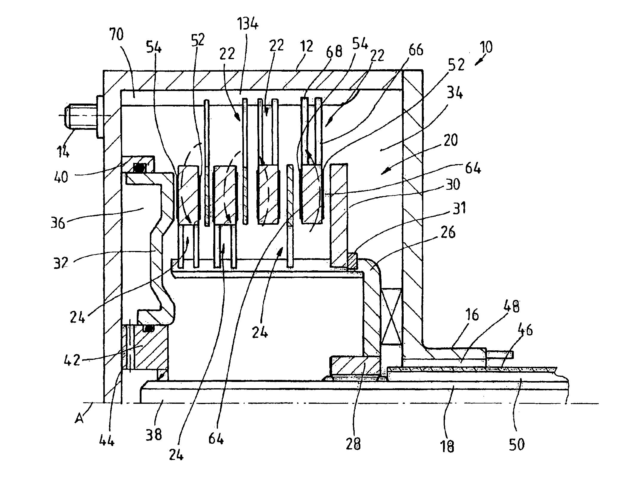
[0060]In FIG. 1, wet clutch arrangement 10 comprises a housing arrangement 12 which can be coupled via a plurality of fastening elements and a coupling element (not illustrated), such as, for example, a flexiplate, to a drive shaft, for example a crankshaft of an internal combustion engine, for rotation together. On the axial side which is situated at a distance from the coupling to the drive shaft, the housing arrangement 12 has a housing hub 16 which engages, for example, in a transmission arrangement (not illustrated) where it drives a fluid-conveying pump such that it rotates. An output shaft 18 which protrudes with its free end into the interior 20 of the housing arrangement 12 is arranged concentrically to the housing hub 16. This output shaft 18 may, for example, be a transmission input shaft.

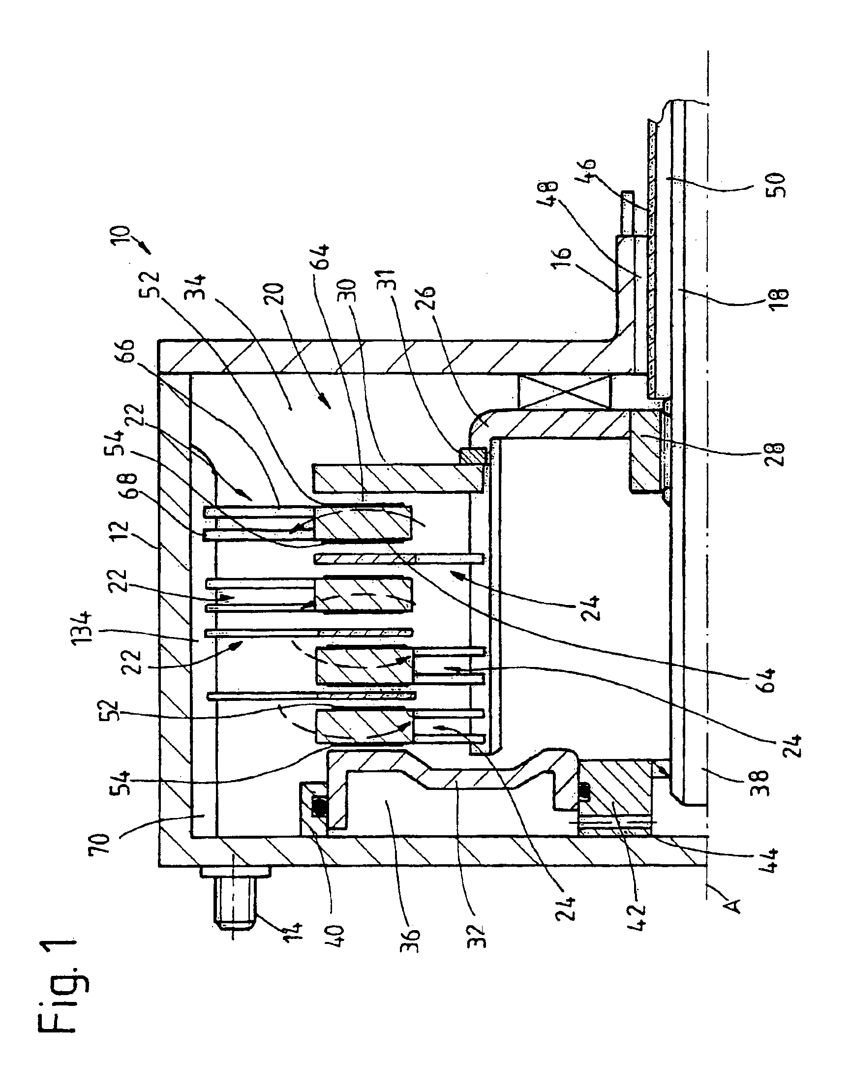
[0061]A plurality of first friction elements 22 which are coupled to the housing arrangement 12 for rotation together is provided in the housing arrangement 12. Furthermore, a plurality ...


PUM


Abstract

A clutch arrangement, especially for a motor vehicle, comprising a housing arrangement (12) which is filled or which can be filled with fluid, at least one first friction element (22) which can be jointly rotated with the housing arrangement (12) and at least one second friction organ (24) which can be jointly rotated with an output element (18) and which can be brought to rest against the at least one first friction element (22) in order to produce at least one interactive friction effect. At least one friction element (22, 24) is embodied in such a way that fluid can circulate around at least certain areas of the friction elements (22, 24).

Description

PRIORITY CLAIM[0001]This is a U.S. national stage of application No. PCT / EP02 / 00899, filed on 29 Jan. 2002. Priority is claimed on that application and on the following application(s): Country: Germany, Application No.: 101 10 097.3, Filed: 02 Mar. 2001; Country: Germany, Application No.: 101 25 628.0, Filed: 25 May 2001.BACKGROUND OF THE INVENTION[0002]1. Field of the Invention[0003]The present invention relates to a clutch arrangement, in particular for a motor vehicle, comprising a housing arrangement which is filled or can be filled with fluid, at least one first friction element which can be rotated together with the housing arrangement, and at least one second friction element which can be rotated together with an output element and can be brought to rest against at least one first friction element in order to produce a frictional interaction.[0004]2. Description of the Related Art[0005]A clutch arrangement of this type, which is generally also known as a wet clutch, is disclo...

Claims


Application Information

Patent Timeline
Patent Type & Authority Patents(United States)
IPC IPC(8): F16D13/58F16D25/00F16D13/72F16D25/12
CPCF16D25/123F16D13/72F16D13/648
Inventor SASSE, CHRISTOPH
Owner ZF FRIEDRICHSHAFEN AG
Why Eureka
Try Eureka