
Paper processing apparatus and cutter unit

Inactive Publication Date: 2005-06-28
FUJIFILM BUSINESS INNOVATION CORP
View PDF16 Cites 112 Cited by
  • Summary
  • Abstract
  • Description
  • Claims
  • Application Information

AI Technical Summary

Benefits of technology

[0011]Another object of the invention is to provide a paper processing apparatus in which ease of use with respect to the user is improved.
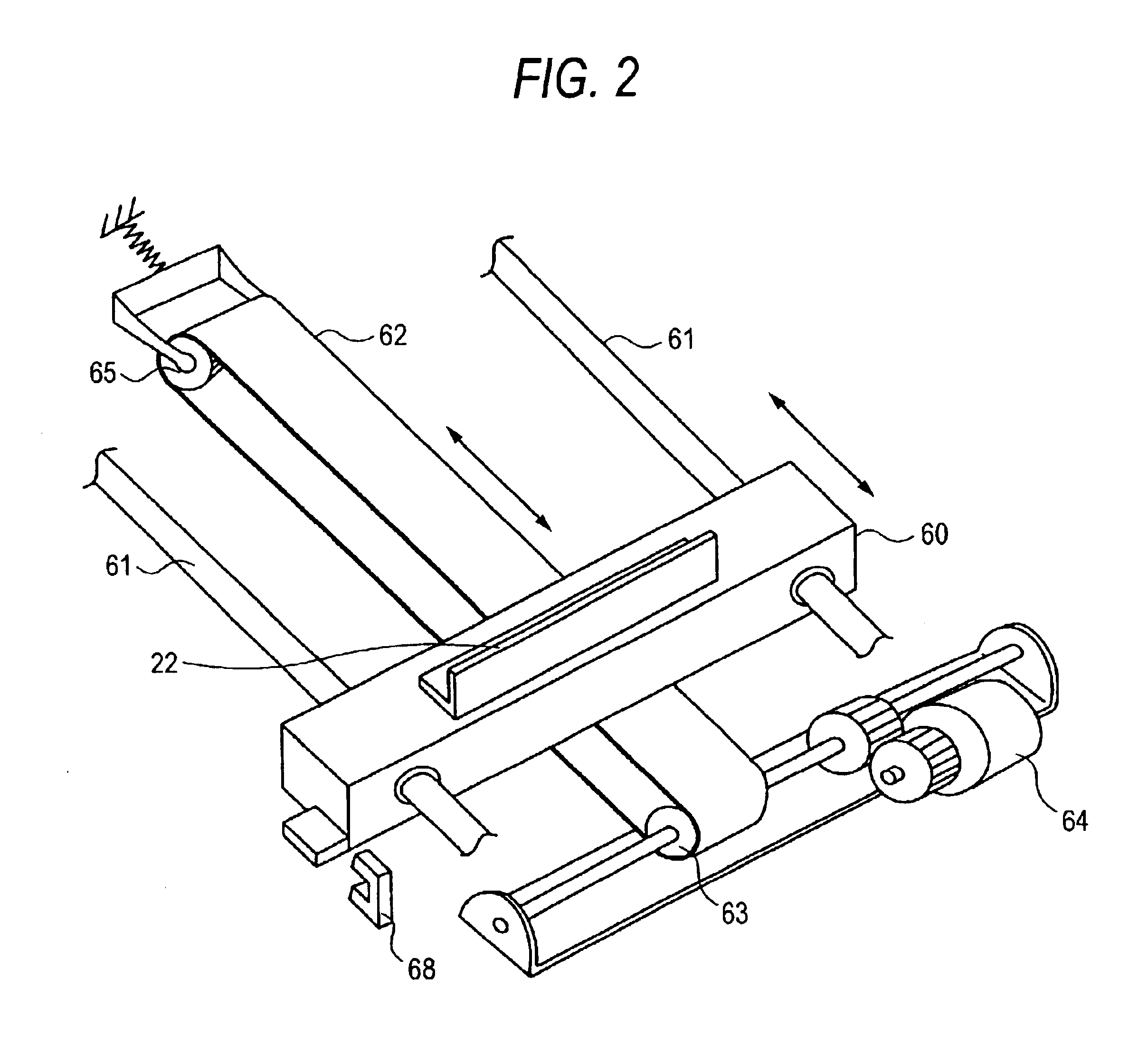
[0013]The cutting section cuts the paper stack by rotating and horizontally moving a round blade. When the round blade is characterized by a cantilevered structure, it becomes easy to dispose, near the round blade, holding section for holding the paper stack to be cut by the cutting section. Moreover, the cutting section can move the blade at a time during which paper sheets of a predetermined number for forming a subsequently processed paper stack are being accommodated with respect to the paper stack accommodating section. Also, another aspect of the invention can be characterized by further including paper binding section for binding a center portion of the paper stack accommodated by the paper stack accommodating section, with the folding section folding the paper stack from a bound portion of the paper stack whose center portion has been bound by the paper binding section.

Problems solved by technology

However, because the guillotine format is employed, it is necessary for the stroke of the cutting blade to be large, which results in the overall apparatus becoming large.
It also becomes necessary to dispose the cutting blade across the entire width of the paper, which results in an unavoidable increase in the cost of the cutting blade.
Furthermore, there has not been much freedom with respect to places where the cutting device can be disposed because the cutting device itself becomes larger (e.g., the discharge port must be disposed downstream of the device), and it has been difficult to provide a paper processing apparatus that is easy to use from the standpoint of the user.

Method used


Image

  • Paper processing apparatus and cutter unit
  • Paper processing apparatus and cutter unit
  • Paper processing apparatus and cutter unit

Examples


Embodiment Construction

[0029]An embodiment of the present invention will be described below with reference to the attached drawings.

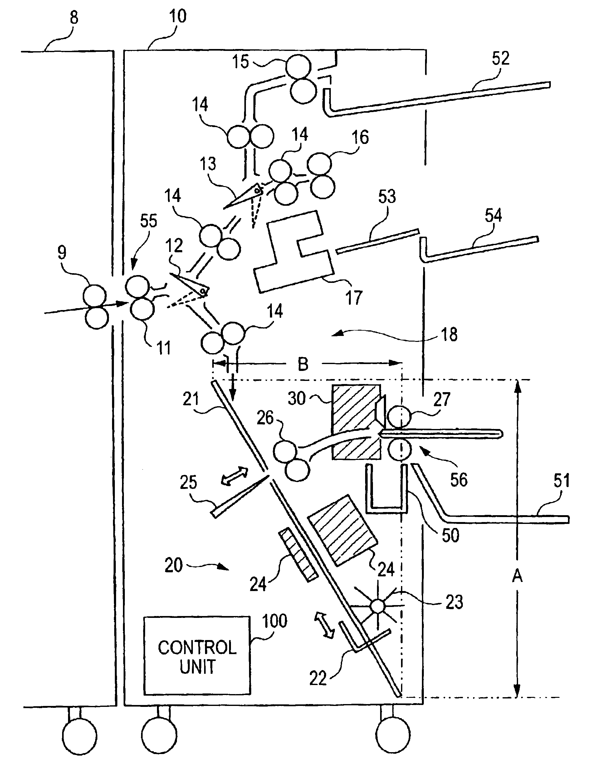
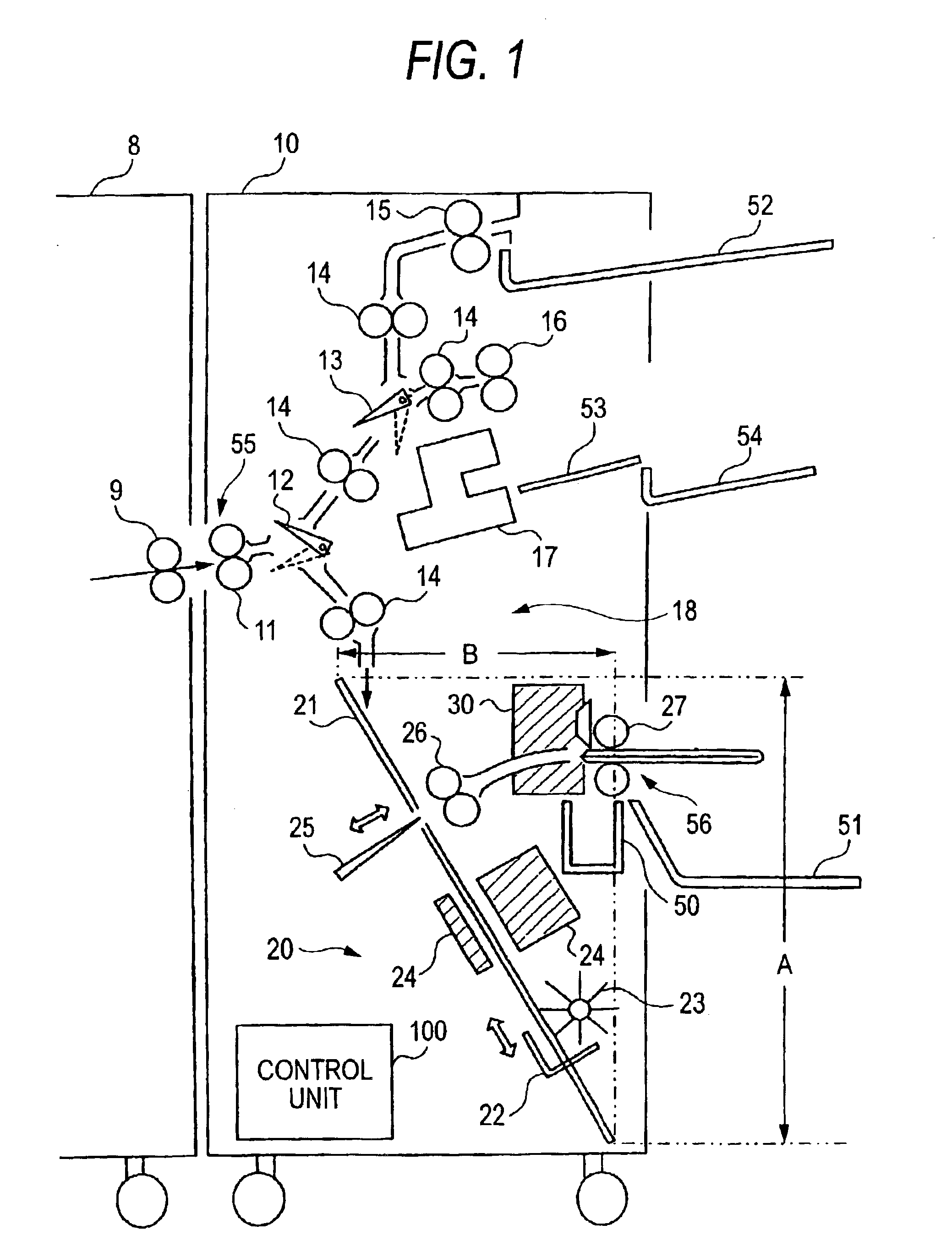
[0030]FIG. 1 is a view showing the overall structure of a paper processing apparatus to which the present embodiment is applied. A paper processing apparatus 10 is connected to an image forming apparatus 8, such as a copying machine or a printer that forms a color image by electrophotography, and is used as a post-processing apparatus. The paper processing apparatus 10 includes, in addition to output for which post-processing is not to be effected and output of end-bound booklets, a small booklet creation section 20 that creates small booklets that have been bound.

[0031]The paper processing apparatus 10 includes: a paper carry-in port 55, which receives printed paper (sheets) outputted via discharge rollers 9 of the image forming apparatus 8; inlet rollers 11, which are disposed near the paper carry-in port 55 and are a pair of rollers that receive the paper; a first gate 12,...


PUM

PropertyMeasurementUnit
Timeaaaaaaaaaa

Abstract

A paper processing apparatus that includes: a paper carry-in port, which is disposed at one side surface of the paper processing apparatus; a center-bound paper discharge port, which is disposed at another side surface opposite from the paper carry-in port; a center-binding compilation tray, which extends from an upper direction of the one side surface to a lower direction of the other side surface, and aligns and accommodates plural sheets of paper conveyed from the paper carry-in port; a center-binding stapler, which binds a predetermined portion of the paper stack that is accommodated and aligned; a folding knife, which folds the bound paper stack; a rotary cutter unit, which is disposed vertically above the center-binding compilation tray and cuts the folded paper using a horizontally moving blade.

Description

[0001]The present disclosure relates to the subject matter contained in Japanese Patent Application No. 2002-364918 filed on Dec. 17, 2002, which is incorporated herein by reference in its entirety.BACKGROUND OF THE INVENTION[0002]1. Field of the Invention[0003]The present invention relates to a paper processing apparatus that processes paper (sheets) discharged from an image forming apparatus, such as a printer or a copying machine, and in particular relates to a paper processing apparatus including a paper cutting mechanism.[0004]2. Description of the Related Art[0005]Many proposals have conventionally been made in regard to paper processing apparatus in which recorded paper (sheets) that is discharged from an image forming apparatus, such as a printer or a copying machine, is retrieved as a bound book. For instance, paper processing apparatus have been proposed in which paper that is discharged from an image forming apparatus and stacked is bound in a central portion thereof, the...

Claims


Application Information

Patent Timeline
IPC IPC(8): B42C1/12B65H45/12B65H35/04B65H45/18B26D1/20B42B4/00B65H35/08B65H37/04B65H37/06B65H45/28
CPCB42C1/12B65H35/04B65H45/18Y10S83/934B65H2301/51512B65H2301/515323B65H2301/4505B65H2701/1829Y10T83/9403
Inventor AWANO, HIROAKI
Owner FUJIFILM BUSINESS INNOVATION CORP
Learn More