Liquid discharge head and method for manufacturing recording head

a liquid discharge head and manufacturing technology, applied in printing and other directions, can solve the problems of unfavorable discharge characteristics or quality, unfavorable pressure on the discharge characteristics of ink droplets, and part of ink filled in the bubbling chamber is pushed back unavoidably to the supply path, so as to enhance the discharge speed of liquid droplets, suppress the pressure exerted by bubbles

Inactive Publication Date: 2005-06-28
CANON KK
View PDF16 Cites 25 Cited by
  • Summary
  • Abstract
  • Description
  • Claims
  • Application Information

AI Technical Summary

Benefits of technology

[0015]Here, the present invention is designed to attempt higher discharge speed of liquid droplets, as well as to stabilize the discharge amount thereof. It is an object of the invention to provide a liquid discharge head for which the discharge efficiency of liquid droplets are enhanced, and also, to provide the method of manufacture therefor.
[0017]Also, for the liquid discharge head thus structured, the height, the width, or the sectional area of flow path in the nozzle is changed, and the structure is arranged so that the volume of ink is gradually reduced in the direction from the base plate to the discharge port. Then, the structure is arranged to provide such a configuration that in the vicinity of the discharge port, when liquid droplet flies, the flying liquid droplet flies vertically to the base plate, and also, to provide the function to straighten (rectify) the liquid flow. Also, when liquid is discharged, it is made possible to suppress the event that the liquid, which is filled in the bubbling chamber, is pushed out to the supply path side by the bubble, which is generated in the bubbling chamber. As a result, in accordance with this liquid discharge head, the occurrence of variation is suppressed in the discharge volumes of liquid droplets to be discharged, and the discharge volume is secured exactly. Also, for this liquid discharge head, when liquid droplet is discharged, the bubble, which is developed in the bubbling chamber, abuts the inner walls of the control portion in the bubbling chamber, which is formed by the portion having difference in level. As a result, the loss of pressure exerted by bubble can be suppressed. Therefore, in accordance with this liquid discharge head, it becomes possible to secure the bubble developed in the bubbling chamber in good condition sufficiently, hence enhancing the discharge speed of liquid droplet.

Problems solved by technology

On the other hand, this ink discharge method characteristically has weakness in that the heat and others, which are generated by the electrothermal converting element, are accumulated in the liquid discharge head to cause the volumes of flying ink droplets to vary; the cavitation resulting from bubble extinction may produce unfavorable effect on the electrothermal converting element; and the air dissolved into ink may become remaining bubbles in the liquid discharge head.
Such weakness may exert unfavorable influence on the discharge characteristics of ink droplets or the quality of recorded images in some cases.
Nevertheless, in the conventional liquid discharge head described above, part of ink filled in the bubbling chamber is pushed back unavoidably to the supply path when ink droplet is discharged by the developed bubble in the bubbling chamber.
As a result, the conventional liquid discharge head is encountered with the drawback that the discharge amount of ink droplet tends to be reduced along with the reduction of the volume of ink in the bubbling chamber.
As a result, the conventional liquid discharge head is encountered with a problem that the discharge speed of ink droplet is reduced along the reduction of bubble pressure.
Also, for the conventional liquid discharge head, there is a problem that the volume of small amount of ink filled in the bubbling chamber is caused to vary due to the bubble that is developed in the bubbling chamber, and therefore, the discharge amount of ink droplet is caused to vary accordingly.

Method used


Image

  • Liquid discharge head and method for manufacturing recording head
  • Liquid discharge head and method for manufacturing recording head
  • Liquid discharge head and method for manufacturing recording head

Examples


first embodiment

(First Embodiment)

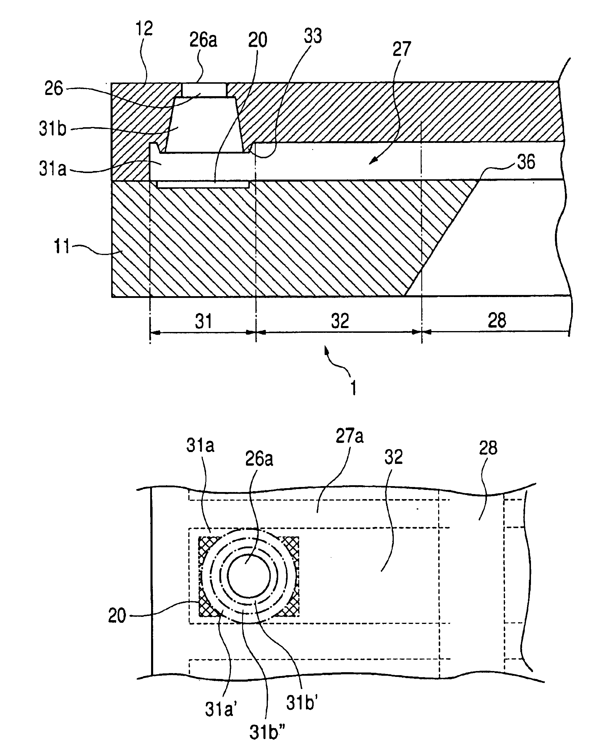
[0039]Although details will be described later, the recording head 1 of a first embodiment is structured, as shown in FIG. 1, with the partition walls extended from the discharge port to the vicinity of supply port in order to form the nozzle that serves as the ink flow path individually for each of the plural heaters serving as heat-generating resistive element. For the liquid discharge head of the kind, the ink discharge means, to which the ink jet recording method is applicable, is provided as disclosed in the specifications of Japanese Patent Application Laid-Open Nos. 04-10940 and 04-10941. Then, the bubble, which is generated at the time of ink discharge, is communicated with the air outside through the discharge port.

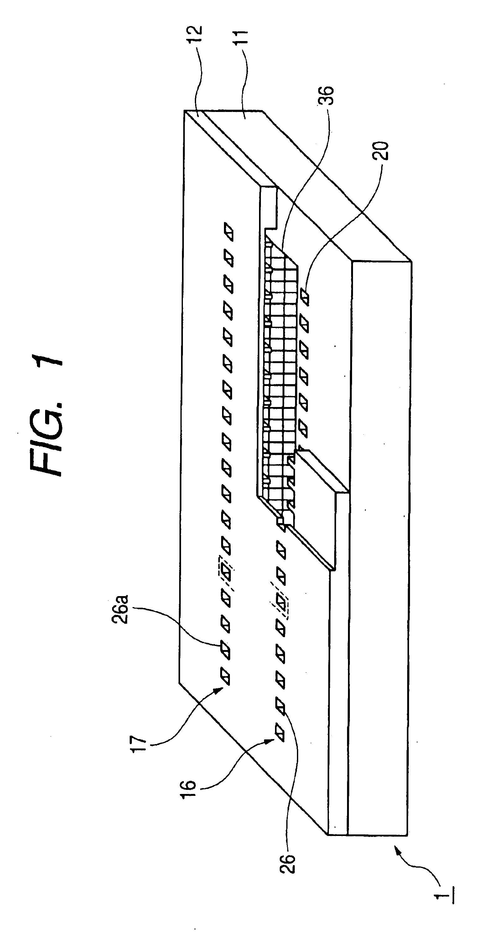
[0040]Then, the liquid discharge head 1 is provided with a first nozzle array 16 in which plural heaters and plural nozzles are provided, and the longitudinal direction of each nozzle is arranged in parallel, and a second nozzle array 17 arrange...

second embodiment

(Second Embodiment)

[0099]In accordance with the first embodiment, the second bubbling chamber 31b, which is configured to be in the form of truncated cone, is formed on the first bubbling chamber 31a, and the sidewalls of the second bubbling chamber 31b are inclined to the plane orthogonal to the main surface of the element base plate 11, and contracted in the direction toward the discharge port portion 26 at an inclination of 10 to 45°, and then, the structure is arranged so that on the circumferential portion of the upper face of the first bubbling chamber 31a in parallel with the main surface of the element base plate 11, which is in contact with the opening communicated with the second bubbling chamber 31b, the extrusion 33 that surrounds the opening and directed toward the main surface of the element base plate 11 is formed continuously. Here, for the liquid discharge head 2 in accordance with a second embodiment, the description will be made of the structure in which ink fille...

third embodiment

(Third Embodiment)

[0127]With reference to the accompanying drawings, the brief description will be made of the liquid discharge head 3 in accordance with a third embodiment. Here, the height of the first bubbling chamber of the liquid discharge head 2 described above is made smaller still, and the height of the second bubbling chamber thereof is made larger. In this respect, for the liquid discharge head 3, the same reference marks are applied to the same members of the liquid discharge heads 1 and 2 described earlier, and the description thereof will be omitted. As in the first embodiment, the bubbling chamber 66 of the liquid discharge head 3 of the third embodiment is provided with the first bubbling chamber 66a in which bubble is generated by the heater 20, and the second bubbling chamber 66b arranged on the midway from the first bubbling chamber 66a to the discharge port portion 63. The structure is arranged so that the sidewalls of the second bubbling chamber 66b are inclined ...


PUM


Abstract

A liquid discharge head includes a first bubbling chamber, a second bubbling chamber arranged thereon, and a discharge port portion communicated with the second bubbling chamber with a difference in level. The sidewalls of the second bubbling chamber contract in the direction toward the discharge port at an inclination of 10 to 45°. On the circumferential portion of the upper face of the first bubbling chamber in contact with an opening communicated with the second bubbling chamber, an extrusion is formed continuously to surround the opening, in the direction toward the main surface of the element base plate.

Description

BACKGROUND OF THE INVENTION[0001]1. Field of the Invention[0002]The present invention relates to a liquid discharge head for recording on a recording medium by discharging liquid droplets, such as ink droplets. The invention also relates to the method of manufacture therefor. More particularly, the invention relates to a liquid discharge head that performs ink jet recording.[0003]2. Related Background Art[0004]The ink jet recording method is one of the so-called non-impact recording methods. The ink jet recording method is capable of performing high-speed recording, and the noises, which are generated at the time of recording, are as small as almost negligible. Also, the ink jet recording method makes it possible to record on various kinds of recording medium, and fix ink on a plain sheet without any particular treatment given thereto. Further, with this method, highly precise images can be obtained at lower costs. With these advantages, the ink jet recording method has been used no...

Claims


Application Information

Patent Timeline
Patent Type & Authority Patents(United States)
IPC IPC(8): B41J2/14B41J2/16B41J2/05
CPCB41J2/1404B41J2/1603B41J2/1623B41J2/1629B41J2/1639B41J2/1645B41J2/1631B41J2002/14475B41J2002/14403
Inventor KUBOTA, MASAHIKOHIYAMA, WATARU
Owner CANON KK
Why Eureka
Try Eureka