Miniature x-ray unit

a miniaturized x-ray and x-ray technology, applied in the field of miniaturized x-ray sources, can solve the problems of difficult use, inconvenient use, and inability to foolproofly use miniaturized x-rays, so as to prevent the irradiation of undesired tissue and prevent the burning of local tissu

Inactive Publication Date: 2005-06-28
SCI MED LIFE SYST
View PDF54 Cites 52 Cited by
  • Summary
  • Abstract
  • Description
  • Claims
  • Application Information

AI Technical Summary

Benefits of technology

[0016]In a preferred embodiment, inflatable (anchoring or positioning) balloons are provided on the exterior of the endoscope to maintain the desired position of the instrument once inserted into the lumen. These balloons may be filled with a gas via catheter lumens connected to a gas or fluid source. Preferably, the balloons are filled with a fluid that absorbs x-rays so that the fluid will help prevent irradiation of undesired tissue. The gas and or fluid will also preferably help to absorb heat generated during the procedure to prevent burning of local tissue. A thermocouple may be positioned on the exterior of the endoscope to monitor the temperature at the treatment site.

Problems solved by technology

Treatment of cancer with x-rays may cause well documented side effects, many of which are due to the broad exposure of the patient to the therapeutic x-rays.
Miniaturized x-rays are not foolproof, however, and still present difficulties upon use.
The x-ray unit generates heat, which can damage adjacent healthy tissue.
Additionally, the x-rays are not localized and irradiate local tissue rather than only irradiating the desired tissue.
It is difficult to maintain the positioning of these instruments at the desired location.
However, the patient becomes “hot”, i.e., radioactive, and the procedure risks exposure of the medical personnel to radiation.

Method used


Image

  • Miniature x-ray unit
  • Miniature x-ray unit
  • Miniature x-ray unit

Examples


Embodiment Construction

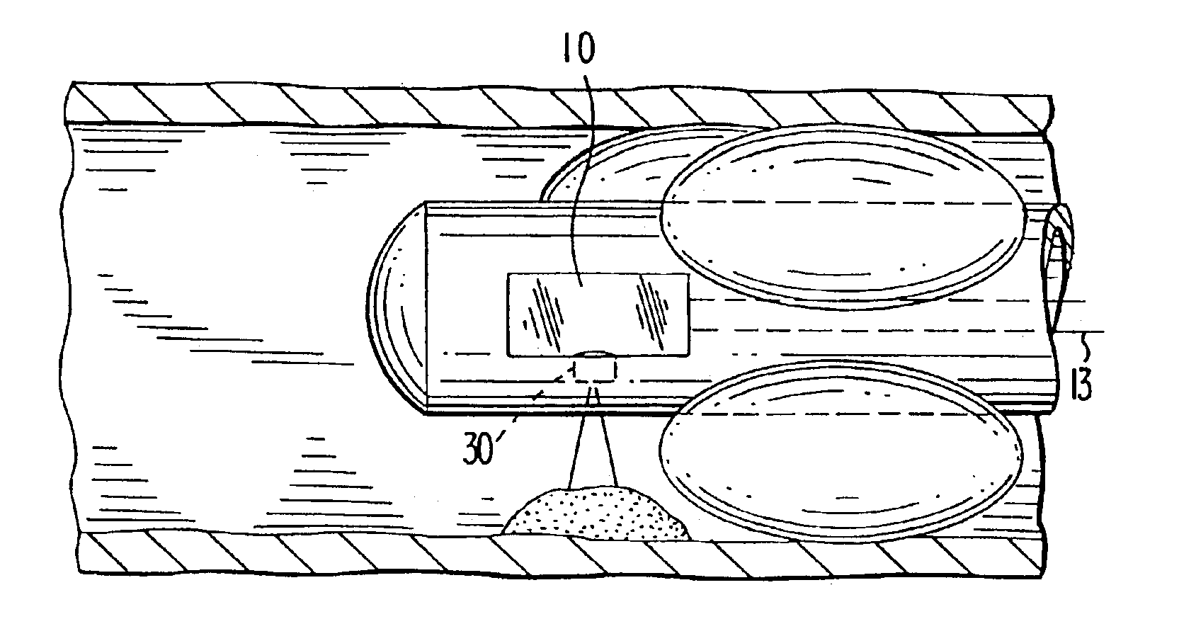
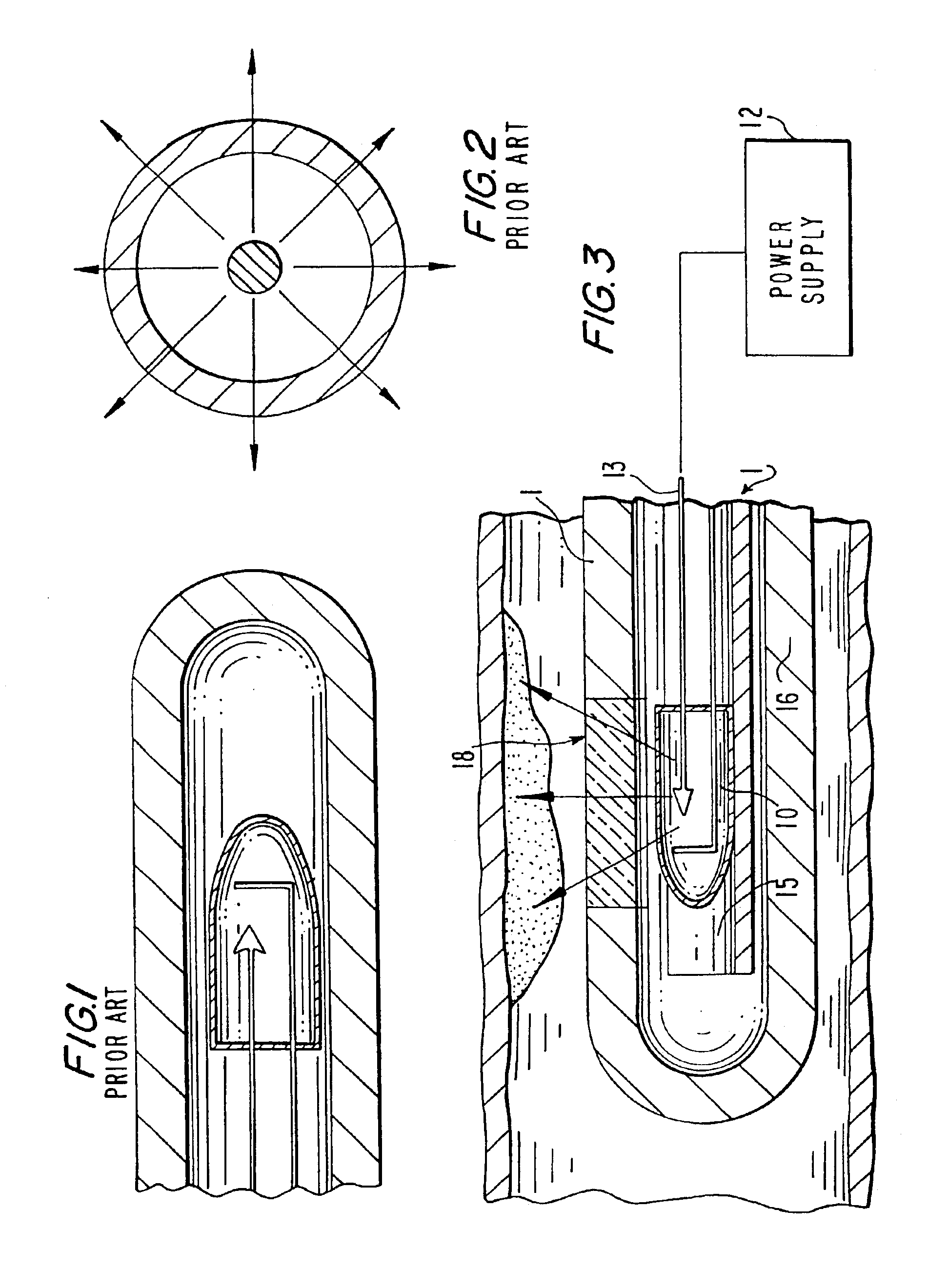
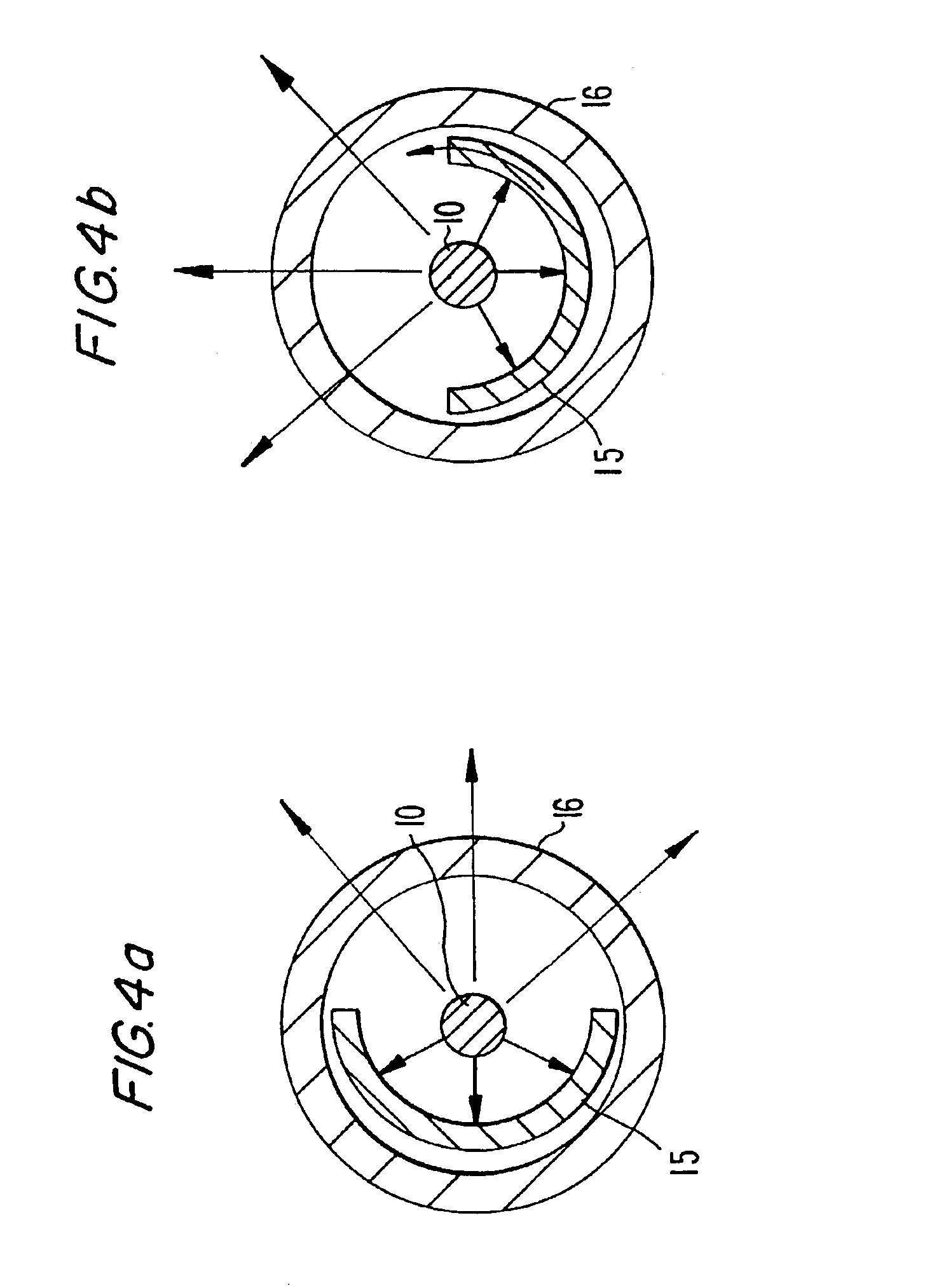
[0031]FIG. 3 is a longitudinal cross section of a preferred x-ray apparatus according to the invention, inserted through the working channel of a endoscope (not shown) in a bodily lumen at a tumor site. The device 1 includes an x-ray source 10 which is connected to power supply 12 by electrically conductive cable 13, e.g. a coaxial cable. X-ray source 10 includes a vacuum tube which maintains vacuum conditions therein and houses the electrodes of the x-ray source. Power supply 12 delivers sufficient energy to x-ray source 10 to generate therapeutically effective x-rays. Typically, voltages of from 10 to 60 kilovolts (kV) are needed to generate x-rays from x-ray source 10. X-ray source 10 is located inside the lumen of x-ray tube 16 which is made of a material substantially or completely impenetrable to x-rays like lead or steel, except where x-ray transparent window 18 is positioned so that x-rays may exit the device and reach the desired site. Window 18 may circumferentially extend...


PUM


Abstract

A miniaturized x-ray apparatus for delivering x-rays to a selected site within a body cavity includes a catheter having at least one lumen and an x-ray transparent window at a distal end thereof; an x-ray source in the lumen adjacent said x-ray transparent window; a movable x-ray shield positioned to direct x-rays from the source through the x-ray transparent window to the selected site.

Description

[0001]This application is a continuation application of Ser. No. 09 / 710,304 filed Nov. 10, 2000 now U.S. Pat. No. 6,540,655, incorporated herein by reference.FIELD OF THE INVENTION[0002]The invention relates to a miniaturized x-ray source situated in a catheter that generates x-rays while minimizing risk from exposure to the x-rays.BACKGROUND OF THE INVENTION[0003]Traditionally, x-rays have been used in the medical industry to view bone, tissue and teeth. X-rays have also been used to treat cancerous and precancerous conditions by exposing a patient to x-rays using an external x-ray source. Treatment of cancer with x-rays may cause well documented side effects, many of which are due to the broad exposure of the patient to the therapeutic x-rays.[0004]To improve medical treatment and diagnosis of patients, minimally invasive endoscopic techniques have been developed and are used to treat a variety of conditions. Endoluminal procedures are procedures performed with an endoscope, a tub...

Claims


Application Information

Patent Timeline
Patent Type & Authority Patents(United States)
IPC IPC(8): A61N5/10
CPCA61N5/1001
Inventor CHIN, YEMPUGSLEY, JR., CHARLES H.HOFFMAN, DAVID W.
Owner SCI MED LIFE SYST
Why Eureka
Try Eureka