Pain inferring device and pain inferring method

a technology of inferring device and inferring method, which is applied in the field of inferring device, can solve the problems of difficult to easily design and give as little pain at the stage of designing the operating portion, and the operator is likely to feel pain, so as to achieve the effect of easy design and minimal pain

Inactive Publication Date: 2005-06-28
KK TOKAI RIKA DENKI SEISAKUSHO
View PDF2 Cites 4 Cited by
  • Summary
  • Abstract
  • Description
  • Claims
  • Application Information

AI Technical Summary

Benefits of technology

[0004]It is an object of the present invention to provide a pain inferring device an

Problems solved by technology

However, operators are likely to feel pain depending on the shape of the uneven surface or on the manner of operating the switch.
However, in order to obtain subjective evaluation of degrees of pain by test subjects, there are

Method used


Image

  • Pain inferring device and pain inferring method
  • Pain inferring device and pain inferring method
  • Pain inferring device and pain inferring method

Examples


second embodiment

(Second Embodiment)

[0044]Next, the pain inferring device according to a second embodiment of the present invention will be described referring to FIGS. 5 to 7.

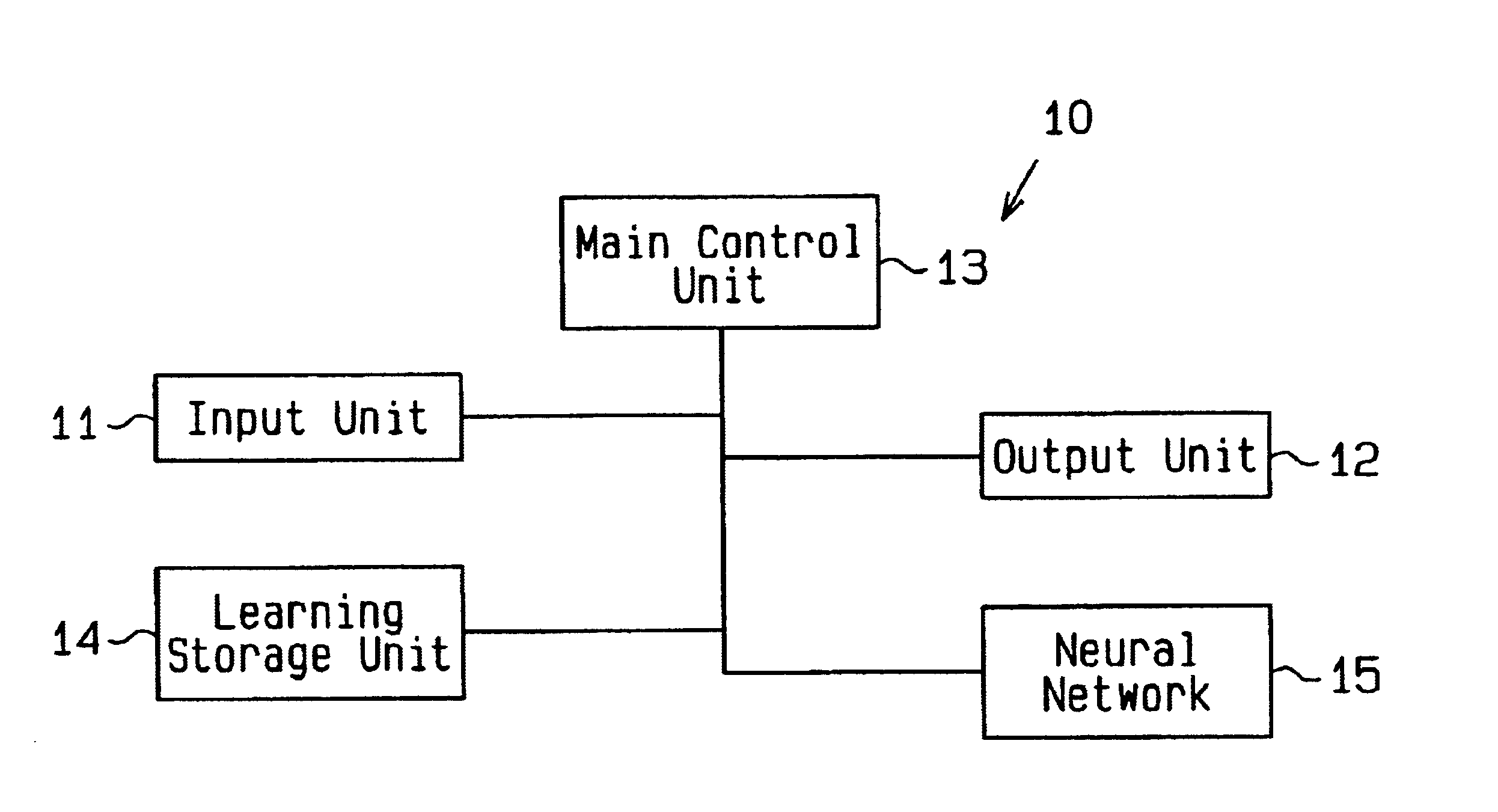
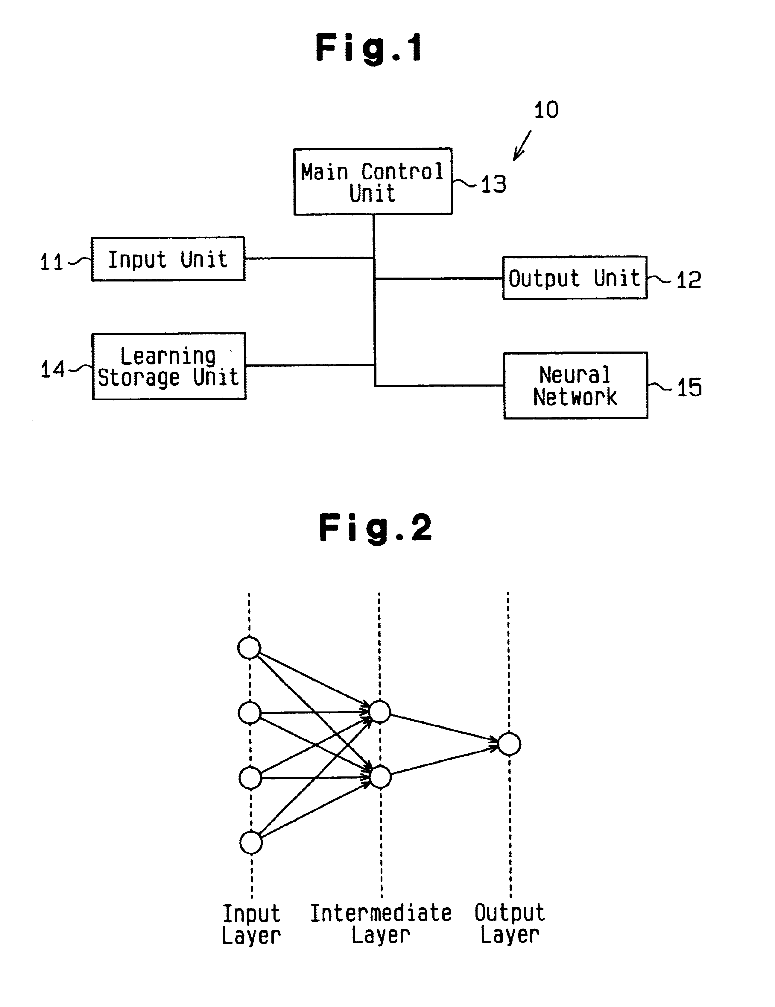
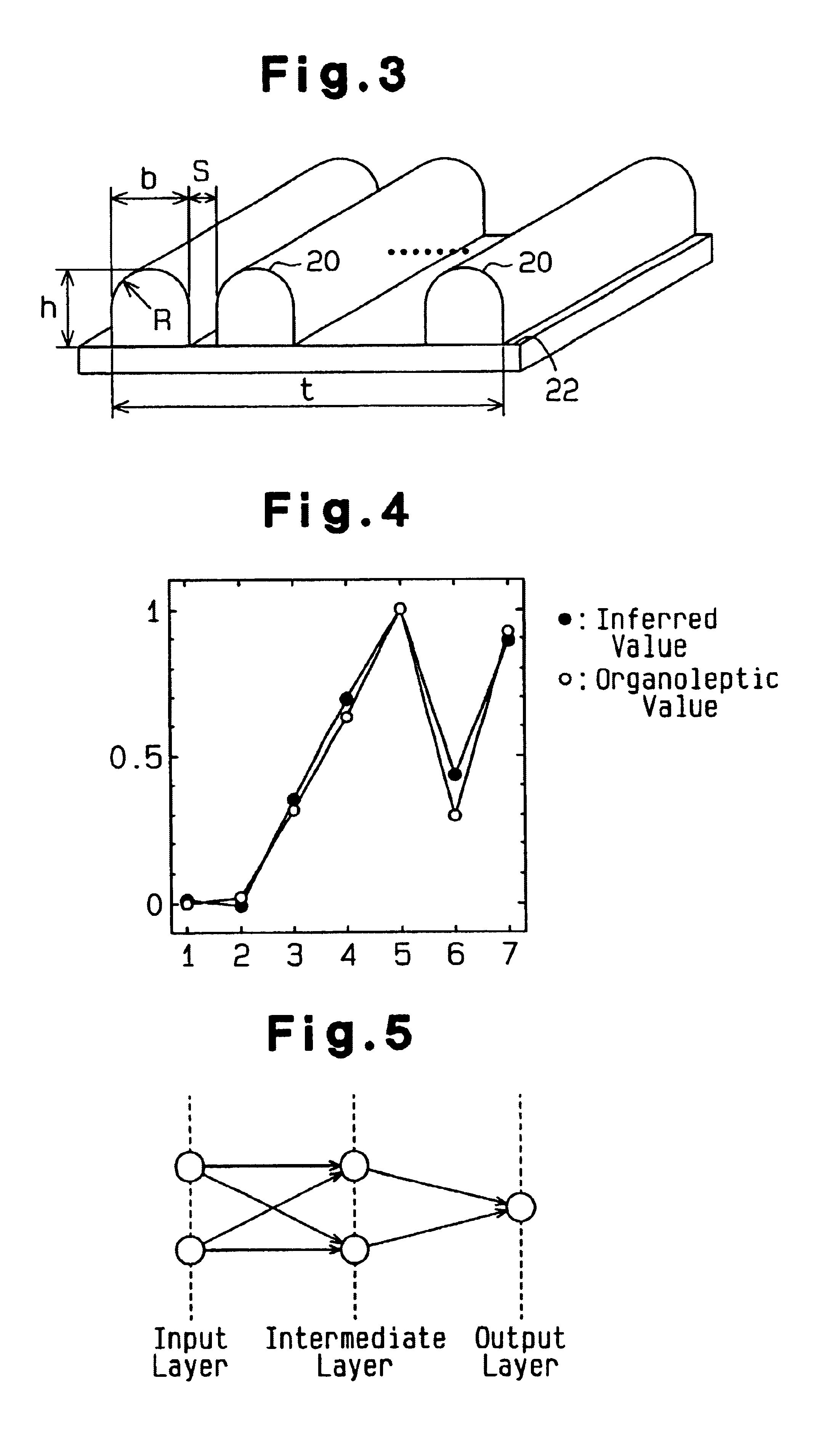
[0045]The pain inferring device 10 of the second embodiment is provided with an input unit 11, an output unit 12, a main control unit 13, a learning storage unit 14 and a neural network 15. The neural network 15 in the second embodiment is of 2-input and 1-output system and includes an input layer, an intermediate layer and an output layer, as shown in FIG. 5. The intermediate layer has two elements (neurons).

[0046]The pain inferring device 10 of the second embodiment is suitable for designing a switch knob (not shown) having a serrated surface, as shown in FIG. 6. In other words, a plurality of ribs 20 each having a triangular cross section are formed parallelwise on the surface of a test piece 22 in the second embodiment.

(Shape Data Setting)

[0047]Shape variables of the ribs 20 include the height h and the apex angle θ thereo...


PUM


Abstract

A pain inferring device for designing a shape giving a subject as little pain as possible when the subject touches the shape. The pain inferring device includes an input unit, an output unit, a main control unit, a learning storage unit, and a neural network. The neural network learns the relationship between the input value of shape data and the output value of the data on the degree of pain when a subject touches a shape. By the learning, an input/output function (namely, the coefficient of coupling of neurons in layers) representing the relationship between the input and output values is defined and stored in the learning storage unit. When the shape data is inputted through the input unit, the neural network infers the degree of pain by using the function stored in the learning storage unit.

Description

TECHNICAL FIELD[0001]The present invention relates to a pain inferring device, more specifically to a pain inferring device for inferring a pain felt by a person when he or she touches a certain shape.BACKGROUND OF THE INVENTIONBACKGROUND ART[0002]Taking a switch for example, operating portion thereof is formed to have an uneven surface so as to prevent slipping of operators' fingers during operation. However, operators are likely to feel pain depending on the shape of the uneven surface or on the manner of operating the switch.[0003]Evaluation of the degree of pain in operators has conventionally been practiced by preparing, at the stage of designing an operating portion, those having various types of uneven surface profiles and allowing test subjects to operate the operating portions thus prepared. An optimum shape is then selected based on evaluation of the degree of pain or on measurement to prepare an operating portion giving minimized pain to operators. However, in order to ob...

Claims


Application Information

Patent Timeline
IPC IPC(8): A61B5/103G06F17/50H01H13/14A61B10/00G06N3/04G06Q10/00G06Q50/00G06Q50/10H01H3/12
CPCA61B5/4824A61B5/7264
Inventor SUZUKI, TAKASHITAKEUCHI, SHUICHINISHIKAWA, MASATOSHINZATO, TAKASHIMIYATA, MASAHIKO
Owner KK TOKAI RIKA DENKI SEISAKUSHO
Why Eureka
Try Eureka