
Heating roller

a heating roller and roller technology, applied in the field of heating rollers, can solve the problems of long rising time of heating rollers, long time to reach predetermined temperature of heating rollers, and problems of heating apparatuses having such a structure, and achieve the effect of reducing rush curren

Inactive Publication Date: 2005-06-28
USHIO DENKI KK
View PDF8 Cites 8 Cited by
  • Summary
  • Abstract
  • Description
  • Claims
  • Application Information

AI Technical Summary

Benefits of technology

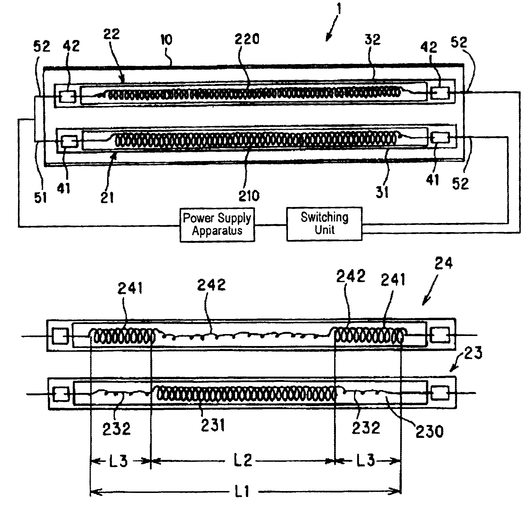
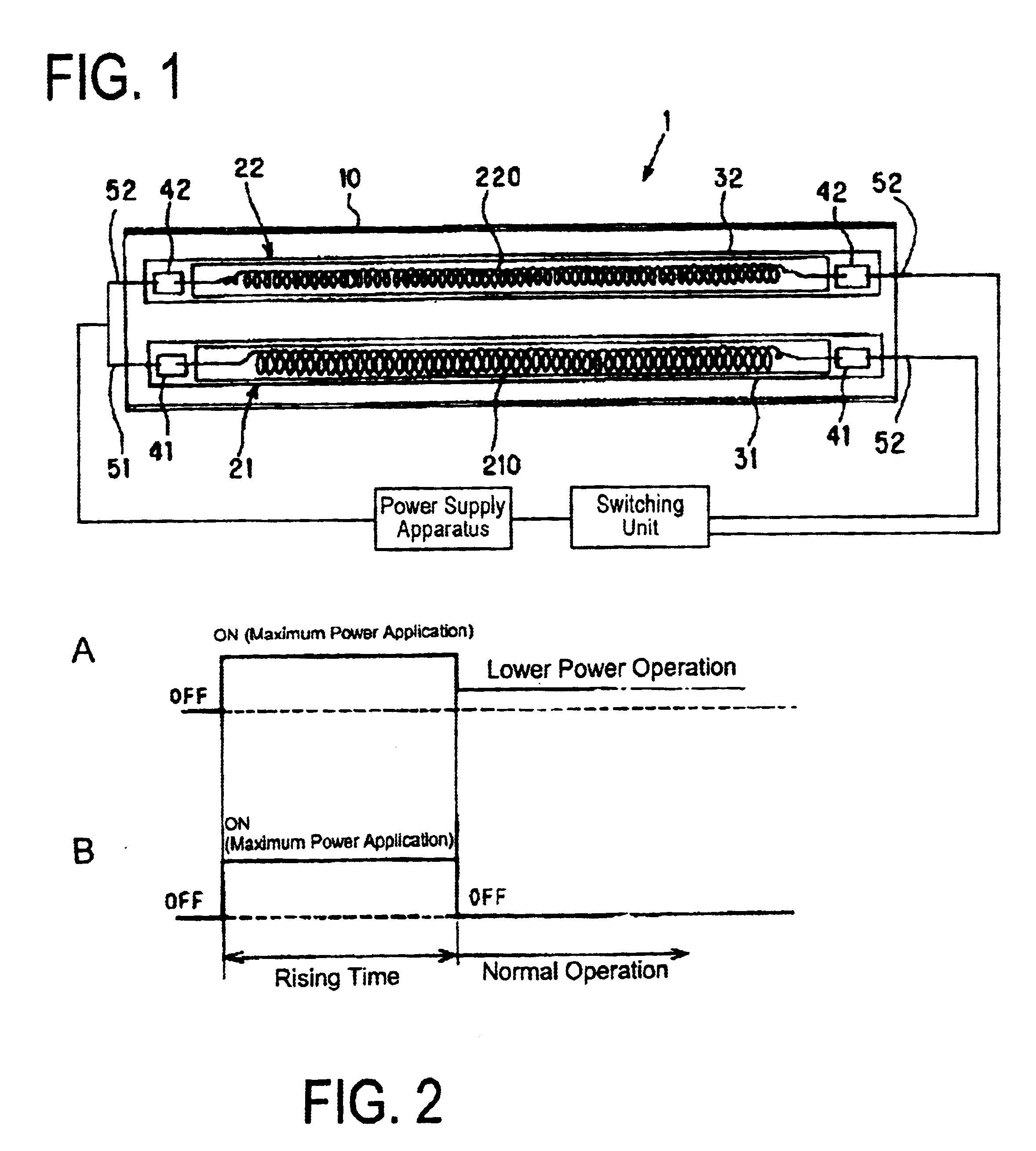
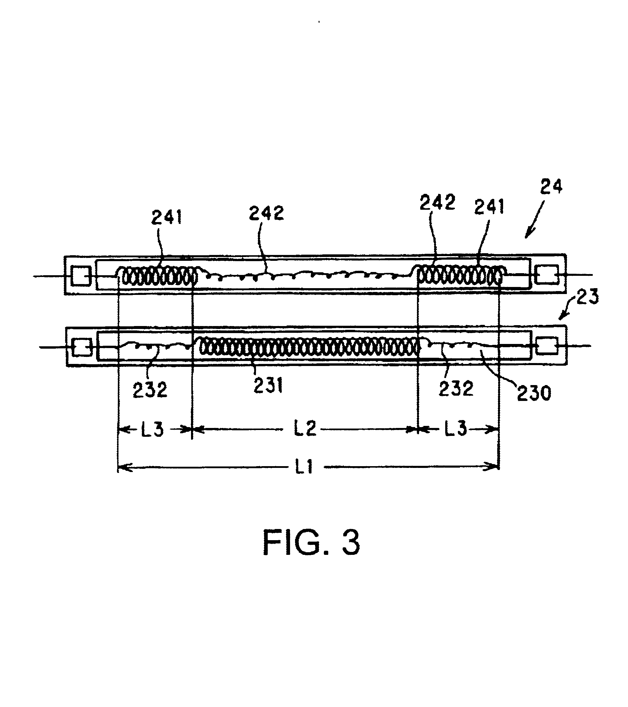
The present invention provides a heater roller that can reduce rush current at the start of power distribution. The heater roller comprises two heater lamps, one made of tungsten and one made of a heating element with greater resistivity. The second heater lamp acts as an auxiliary heater lamp and is turned on at the initial power distribution period. The first heater lamp has at least one non-lighting portion and the second heater lamp has at least one non-lighting portion. The non-lighting portions face each other to minimize the impact of rush current on the circuit. This heater roller structure can reduce the risk of circuit breakage and increase the efficiency of power distribution.

Problems solved by technology

However, the heat apparatuses having such a structure have problems described below.
However, it takes long time to reach a predetermined temperature of the heating roller since output of the heater lamp is not sufficient.
That is, a long rising time of heating roller is necessary.
Since a controlling circuit for reducing rush current needs to be provided in the power supply device, the cost of the power supply device increases and the power supply device also grows in size.
In the heater lamp of the fixing device, there is a problem that the circuit of the device is vulnerable to a rush current since the heater lamp is turned on with maximum input power that is usually close to rated consumption electric power thereby easily causing a break in the circuit.

Method used


Image

  • Heating roller
  • Heating roller
  • Heating roller

Examples


example

[0054]A heating roller according to the second embodiment was prepared in the following specification:

Roller Body 10

[0055]Material: Iron

[0056]External Diameter: 35 mm

[0057]Internal Diameter: 33 mm

[0058]Length: 350 mm

Fixing Heater Lamp 23

[0059]Entire Length: 390 mm

[0060]Valve Material: Quartz glass

[0061]Valve External Diameter: 6 mm

[0062]Valve Radial Thickness: 1 mm

[0063]Filament Material: 50 to 90 ppm potassium doped

[0064]tungsten (Tungsten: more than 99.9%)

[0065]Filament Diameter (Wire Diameter): φ0.29 mm

[0066]Length of Light Emitting Portion: (L1): 195 mm

[0067]Applied Power: 600 W (Voltage: 100 V)

Auxiliary Heater Lamp 24

[0068]Lamp Length: 390 mm

[0069]Valve Material: Quartz glass

[0070]Valve External Diameter: 6 mm

[0071]Valve Radial Thickness: 1 mm

[0072]Material of Filament: Cantal

[0073]Filament Diameter (Wire Diameter): φ0.5 mm,

[0074]Length of light emitting portion (L2): 335 mm

[0075]Applied Power: 600 W (Voltage: 100 V)


PUM

PropertyMeasurementUnit
temperatureaaaaaaaaaa
resistivityaaaaaaaaaa

Abstract

A heating roller has a first heater lamp having a first filament made of tungsten, and a second heater lamp having a second filament wherein the second filament is a heating element whose resistivity value is greater than that of tungsten at a room temperature.

Description

TECHNICAL FIELD OF THE INVENTION[0001]The present invention relates to a heater apparatus for a heating roller of a fixing device provided in an image forming apparatus such as an electrophotographic type printer, copying machine and the like.DESCRIPTION OF RELATED ART[0002]In an image forming apparatus such as a printer, a copying machine and the like that uses an electrophotographic process, a fixing device for fixing a unfixed toner image held on a recording material such as a recording paper sheet, an OHP sheet and the like is provided. For the fixing device, a so-called heating roller is widely used as means for fixing the toner on the paper sheet.[0003]Such a heating roller type fixing device will be explained below, referring to FIG. 5.[0004]In FIG. 5, the fixing device has a heating roller 1 with which a pressure roller 2 is in contact under pressure. A recording paper sheet P, that is, a toner transferred material holding a unfixed toner image To passes through a contact ar...

Claims


Application Information

Patent Timeline
Patent Type & Authority Patents(United States)
IPC IPC(8): H05B3/00G03G15/20H05B3/10H05B3/44
CPCG03G15/2053H05B3/0095H05B3/0066
Inventor SHIMONAKA, MASATOSHI
Owner USHIO DENKI KK
Learn More