Micro-power source

a micro-power source and power supply technology, applied in nuclear engineering, radiation electrical energy, semiconductor devices, etc., can solve the problems of limiting the size, weight, volume and cost of the battery power source, and the dominant constraint on size, weight, volume and cos

Inactive Publication Date: 2005-06-28
NAVY SEC OF THE UNITED STATES
View PDF3 Cites 19 Cited by
  • Summary
  • Abstract
  • Description
  • Claims
  • Application Information

AI Technical Summary

Problems solved by technology

In the case of miniaturized sensors, the predominant limiting constraint on size, weight, volume and cost is the battery power source.

Method used


Image

  • Micro-power source
  • Micro-power source
  • Micro-power source

Examples


Embodiment Construction

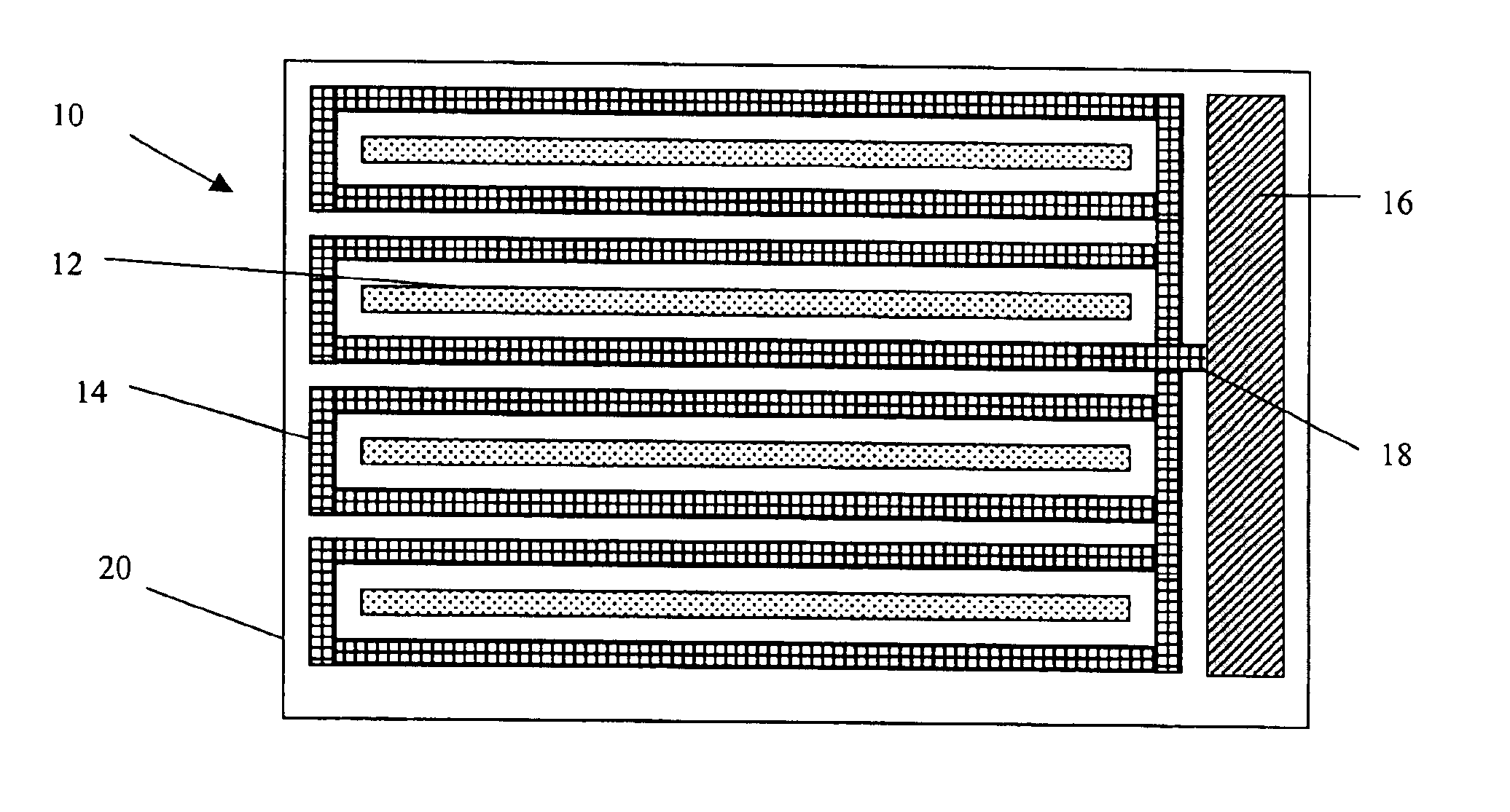
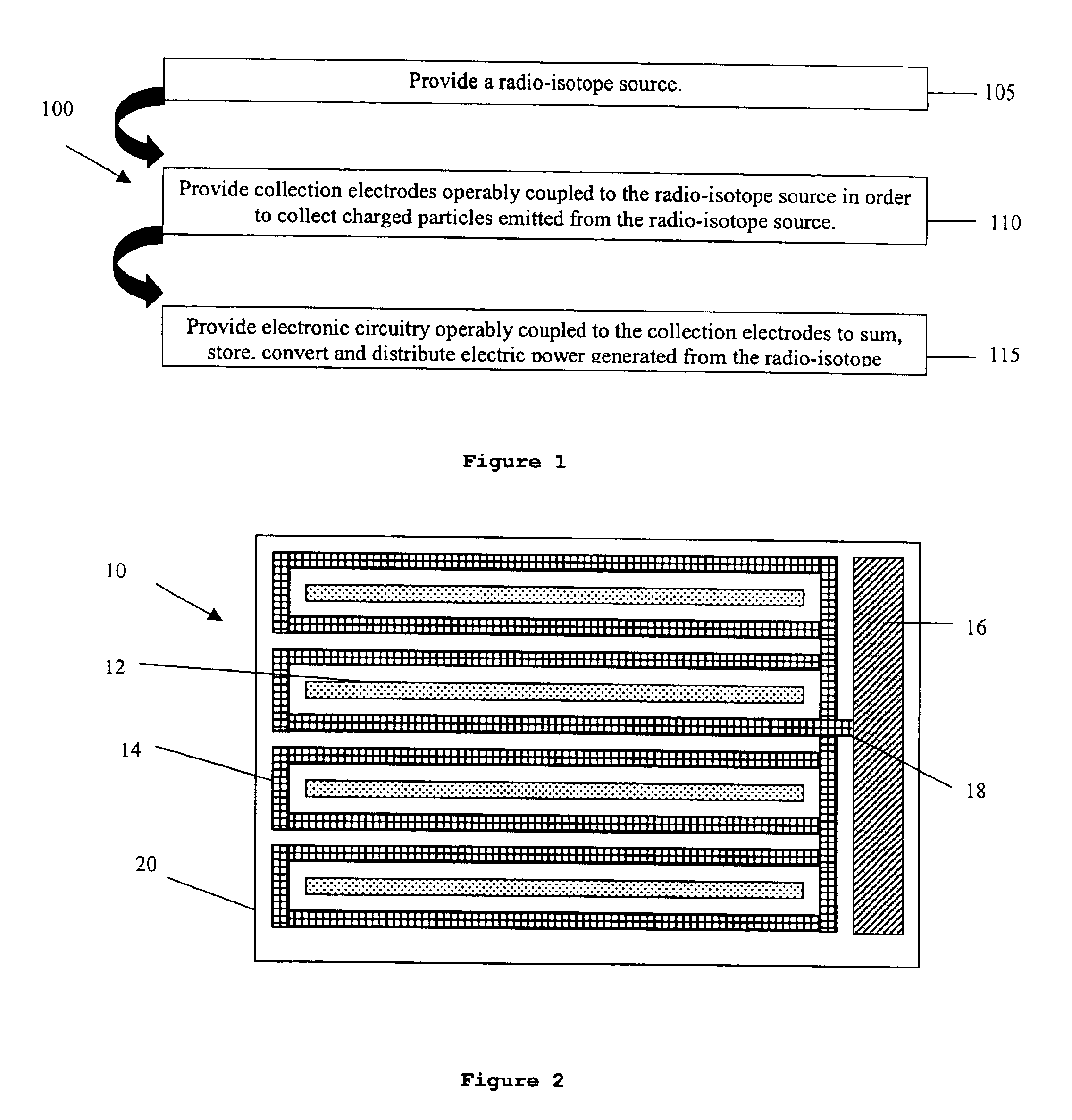
[0009]A micro-power source embodying various features of the present invention is a radioisotope-based apparatus that exploits microelectronic processing techniques to miniaturize the structure and collect and distribute electrical energy. FIG. 1 shows a schematic process 100 of implementing the micro-power source. A radio-isotope source 105, as for example a Ni63 source with a half-life of about 70 to 100 years, emits electrons with energy of about 17 keV through well-known beta-decay. The radio-isotope source may be formed in a quasi-planar geometry compatible with micro-fabrication techniques such as deposition and patterning or electro-plating on a wafer surface. Collection electrodes 110 operably coupled to the radio-isotope source 105 collect charged particles emitted from the radio-isotope source 105. Such collection electrodes 110 may be formed in a hemispherical configuration, cylindrical, planar, or other geometry in order to intercept a desired number of emitted charged p...


PUM


Abstract

A micro-power generator, comprises an electrically insulating substrate; a semiconductor layer affixed to the substrate; electrodes affixed to the semiconductor layer for collecting electrical charges emitted by a radioisotope source; a radio-isotope source interposed between the electrodes; and electrical circuitry operably coupled to the electrodes for transforming the electrical charges into a controlled output.

Description

BACKGROUND OF THE INVENTION[0001]All electronic systems require electrical power in order to operate. For portable systems, typical sources of power are batteries which are sometimes augmented by solar cells for recharging. In the case of miniaturized sensors, the predominant limiting constraint on size, weight, volume and cost is the battery power source. Therefore, a need exists for alternative miniaturized energy sources.BRIEF SUMMARY OF THE INVENTION[0002]A micro-power generator, comprises an electrically insulating substrate; a semiconductor layer affixed to the substrate; electrodes affixed to the semiconductor layer for collecting electrical charges emitted by a radio-isotope source; a radio-isotope source interposed between the electrodes; and electrical circuitry operably coupled to the electrodes for transforming the electrical charges into a controlled output.BRIEF DESCRIPTION OF THE SEVERAL VIEWS OF THE DRAWINGS[0003]FIG. 1 shows a schematic process for implementing a ra...

Claims


Application Information

Patent Timeline
Patent Type & Authority Patents(United States)
IPC IPC(8): G21H1/00H01L21/00H01L31/115
CPCG21H1/06
Inventor SHIMABUKURO, RANDY L.RUSSELL, STEPHEN D.
Owner NAVY SEC OF THE UNITED STATES
Why Eureka
Try Eureka