Antenna apparatus

Inactive Publication Date: 2005-06-28
KK TOSHIBA
View PDF12 Cites 32 Cited by
  • Summary
  • Abstract
  • Description
  • Claims
  • Application Information

AI Technical Summary

Benefits of technology

[0012]It is an object of the present invention to provide an antenna a

Problems solved by technology

However, the antenna shown in FIG. 1 has two, third and second, planar antenna elements, which poses limitations on downsizing of parts mounted on the circuit board 100.
The antenna shown in FIG. 1 requires a long time for design.
A model to be input to an electromagnetic simulation is difficult to formulate.
It takes a long time to optimize

Method used


Image

  • Antenna apparatus
  • Antenna apparatus
  • Antenna apparatus

Examples


Example

(First Embodiment)

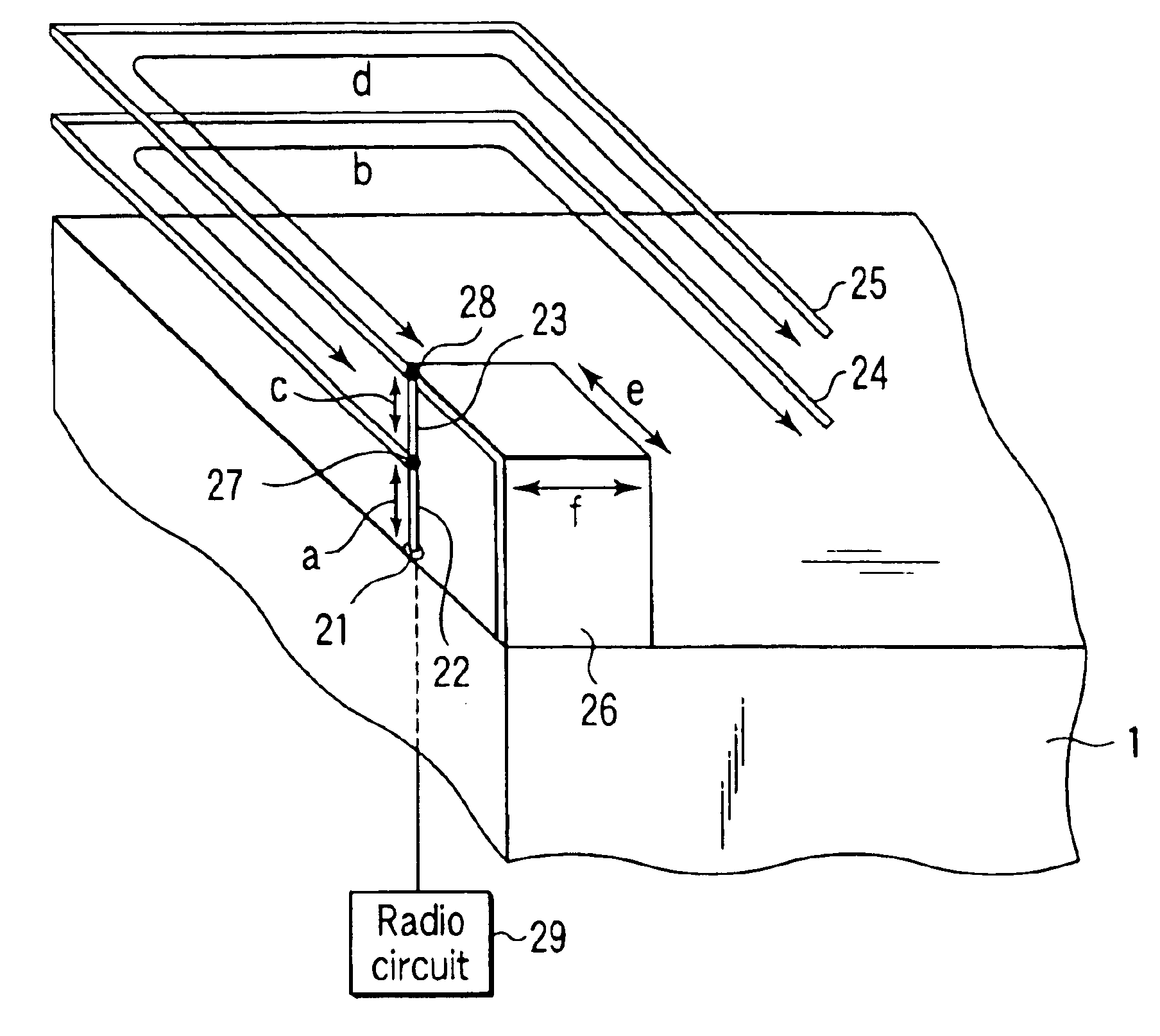
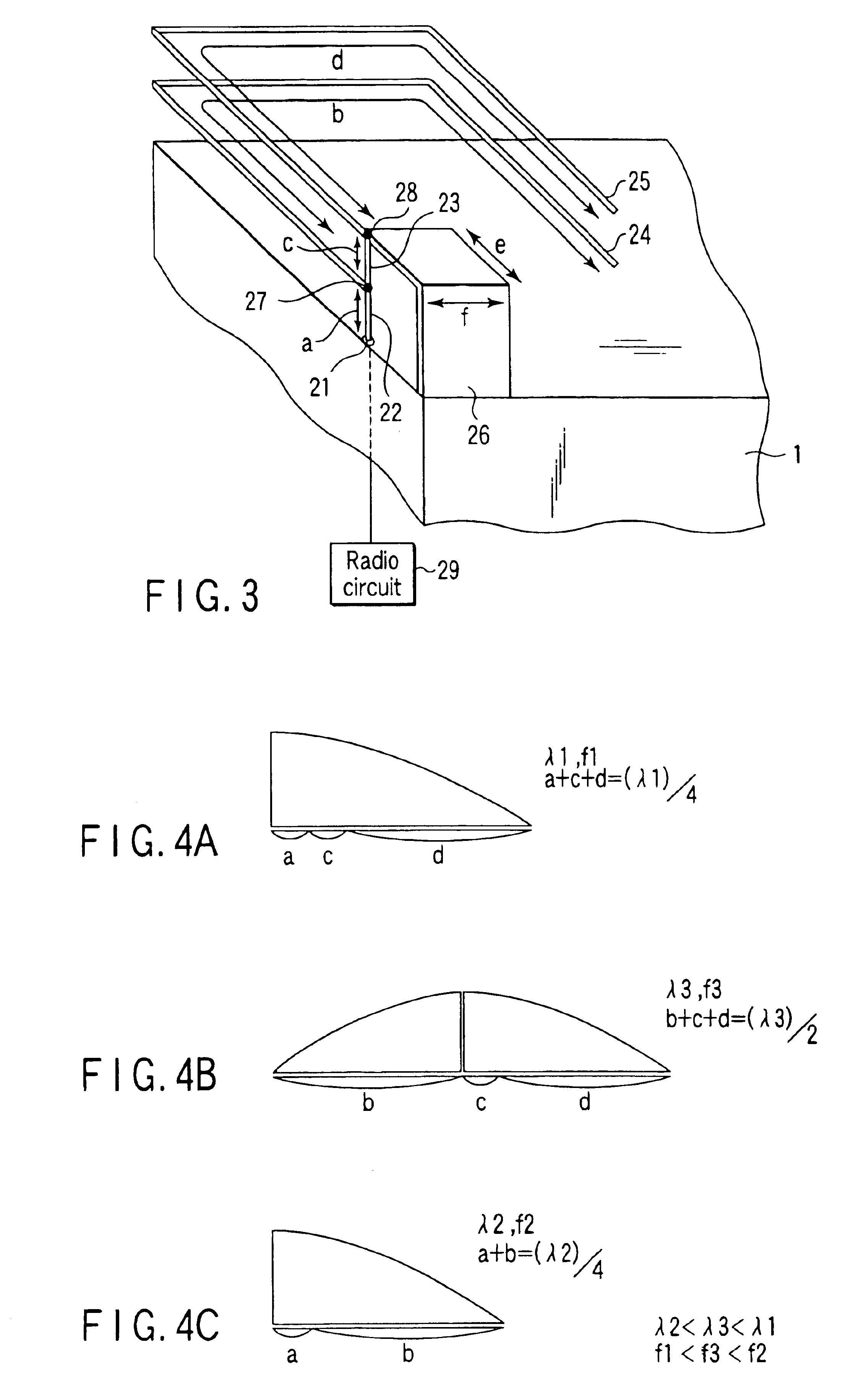
[0063]FIG. 2 shows an arrangement of an antenna 2 according to the first embodiment of the present invention.

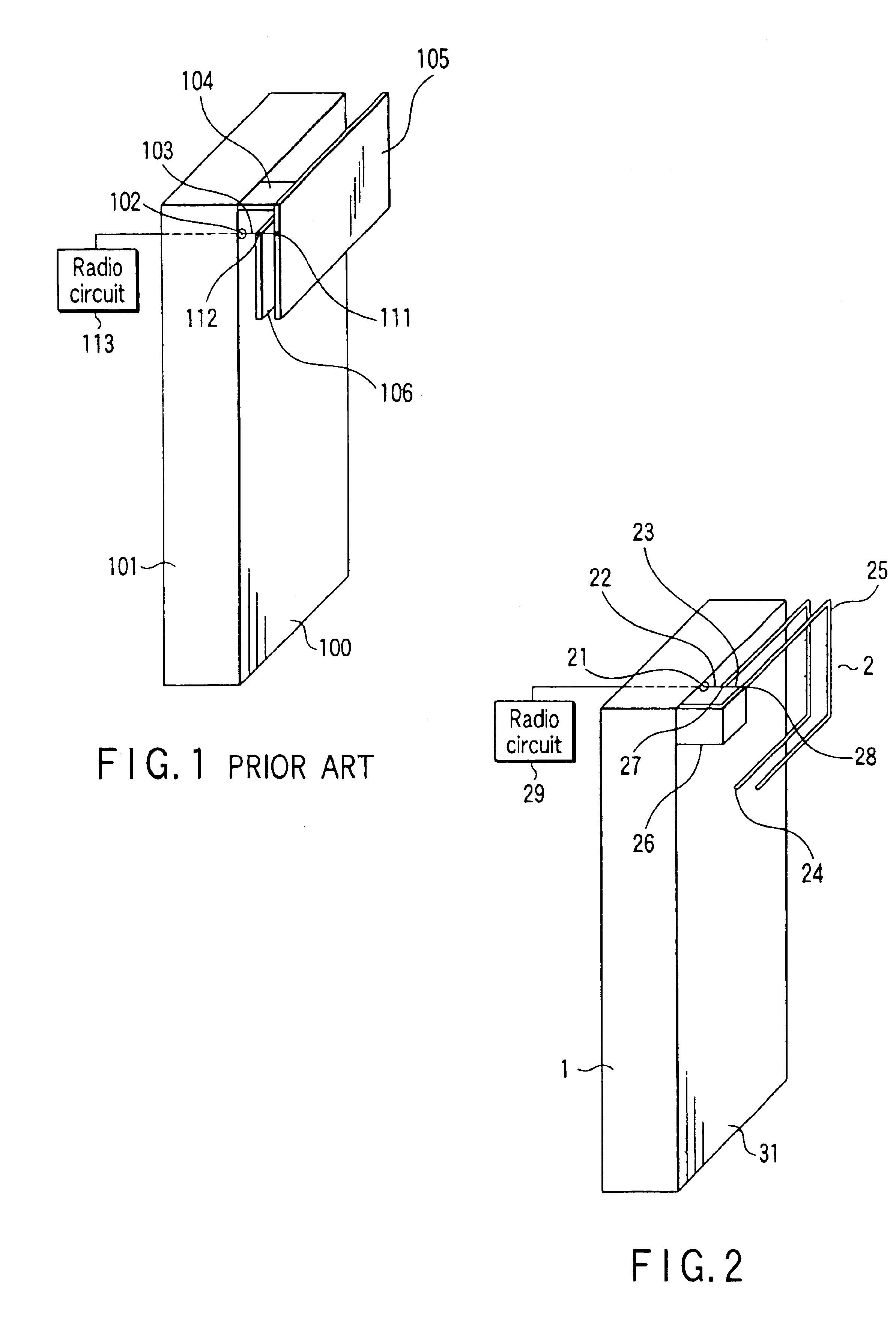
[0064]The antenna 2 according to the first embodiment is installed in a square internal housing 1 formed from a ground conductor inside an external housing made of an insulator such as a plastic in a wireless communication device. A surface on which the antenna 2 of the housing 1 is mounted will be called a ground plane 31. The antenna 2 exchanges signals with a wireless device via a feed point 21 on the housing 1 so as not to electrically connect the antenna 2 and ground plane 31.

[0065]The shape and size of the housing 1 are not particularly limited and can be arbitrarily designed. The feed point 21 can be set at an arbitrary position on the housing 1. In FIG. 2, the feed point 21 is set at the end of the ground plane 31 of the housing 1. However, the following effects can be obtained by adjustment regardless of where the feed point 21 is set on the housing...

Example

(Second Embodiment)

[0152]An antenna formed from a ribbon-like antenna element with the same antenna principle according to the present invention described in the first embodiment will be explained as the second embodiment.

[0153]In general, an antenna uses a ribbon-like antenna element in order to ensure the mechanical strength and reduce the cost. The antenna of the present invention can also adopt a ribbon-like antenna element.

[0154]FIG. 19 shows the arrangement of an antenna according to the second embodiment of the present invention. FIG. 19 also shows the parameters a to f of respective antenna elements in an antenna 2 when each antenna element of the antenna is a ribbon-like antenna element.

[0155]As shown in FIG. 19, linear antenna elements used for this antenna are ribbon-like antenna elements in the second embodiment, whereas these linear antenna elements are wire antenna elements in the antenna 2 according to the first embodiment. The ribbon antenna elements have widths, unl...

Example

(Third Embodiment)

[0171]The antenna 2 shown in FIG. 3 according to the first embodiment has a transmission / reception bandwidth whose lower and upper limit frequencies are 840 MHz and 880 MHz, as shown in FIG. 12B. However, some of devices which comprise the antenna 2 require a wider transmission / reception bandwidth and must reduce upward directivity of radiation from an antenna element parallel to the ground plane. To satisfy these conditions, the gist of the third embodiment is to widen the frequency band and improve the radiation directivity.

[0172]The third embodiment will exemplify an antenna 200 obtained by adding another pair of wire antenna elements parallel to a ground plane that correspond to the third and fourth wire antenna elements 24 and 25 in FIG. 2.

[0173]FIG. 20 shows an arrangement of the antenna 200 according to the third embodiment. The antenna 200 is mounted on a ground conductor (ground plane) 201. Signals are transmitted between, e.g., a wireless device and the a...


PUM


Abstract

An antenna apparatus is constituted by first, second, third, and fourth wire antenna elements and a connection element. The sum of the lengths of the first, second, and fourth wire antenna elements is ¼ the wavelength corresponding to a series-resonance frequency of the first, second, and fourth wire antenna elements. The sum of the lengths of the second, third, and fourth wire antenna elements is ½ the wavelength corresponding to a parallel-resonance frequency of the second, third, and fourth wire antenna elements. The sum of the lengths of the first and third wire antenna elements is ¼ the wavelength corresponding to a series-resonance frequency of the first and third wire antenna elements. The parallel-resonance frequency is higher than the series-resonance frequency of the first, second, and fourth wire antenna elements and lower than the series-resonance frequency of the first and third wire antenna elements.

Description

[0001]This application is a Division of application Ser. No. 10 / 188,755 filed on Jul. 5, 2002, now U.S. Pat. No. 6,683,575.CROSS-REFERENCE TO RELATED APPLICATIONS[0002]This application is based upon and claims the benefit of priority from the prior Japanese Patent Applications No. 2001-205239, filed Jul. 5, 2001; and No. 2001-371772, filed Dec. 5, 2001 the entire contents of both of which are incorporated herein by reference.BACKGROUND OF THE INVENTION[0003]1. Field of the Invention[0004]The present invention relates to an antenna apparatus used as antenna mounted on a surface of a vehicle or used as a built-in antenna for a portable telephone or the like.[0005]2. Description of the Related Art[0006]The antenna of a portable telephone suffers a changeable frequency characteristic depending on the proximity of the user's body or the like. To mitigate the change, the antenna of a portable telephone must be broadband.[0007]An antenna shown in FIG. 1 is a conventional antenna. The anten...

Claims


Application Information

Patent Timeline
IPC IPC(8): H01Q9/04H01Q1/24H01Q9/42H01Q5/10H01Q13/08
CPCH01Q1/243H01Q9/42H01Q9/0442H01Q9/0421
Inventor SEKINE, SYUICHIITO, TAKAYOSHIMURAKAMI, YASUSHISHOKI, HIROKI
Owner KK TOSHIBA
Why Eureka
Try Eureka