Computer vision depth segmentation using virtual surface

Inactive Publication Date: 2005-06-28
MITSUBISHI ELECTRIC RES LAB INC
View PDF7 Cites 84 Cited by
  • Summary
  • Abstract
  • Description
  • Claims
  • Application Information

AI Technical Summary

Benefits of technology

[0018]More particularly, the invention facilitates identifying a location of an object in a physical scene with a stereo camera. A virtual surface is identified in the physical scene, and an approximate disparity set is constructed for the virtual surface. The stereo camera then acquires a main and a reference image of the scene. The reference image is warped according to the disparity set, and the warped image is subtracted from the main image to determine depth residuals of pixels in the main image. Pixels having a substantially non-zero residual are identified as lying on a surface of the object not coincident with the virtual surface. The decision threshold is set according to the level of noise in the images.
[0019]Furthermore, the i

Problems solved by technology

However, computer vision systems, with rare exceptions, are difficult to implement for applications where the visual appearance of objects and the scene change rapidly due to lighting fluctuations.
Under dynamic lighting, traditional segmentation techniques generally fail.
The difficulty of implementation increases for interactive applications that use front-projected or rear-projected displays because the projector will illuminate foreground objects as well as the background.
This makes color tracking and other appearance-based methods difficult, if not impossible to use.
This is computationally time consuming, and therefore unsuitable for applications that demand real-time performance.
For many practical applications that require natural interactions and natural user environments, these constraints are too restrictive.
Any different and unknown illumination dramatically degrades performance of the system, should it work at all.
None of the above techniques accommodate rapidly changing lighting conditions, such as one would get when illuminating background and foreground objects with a dynamic, high-contrast projection display device.
How

Method used


Image

  • Computer vision depth segmentation using virtual surface
  • Computer vision depth segmentation using virtual surface
  • Computer vision depth segmentation using virtual surface

Examples


Embodiment Construction

System Structure

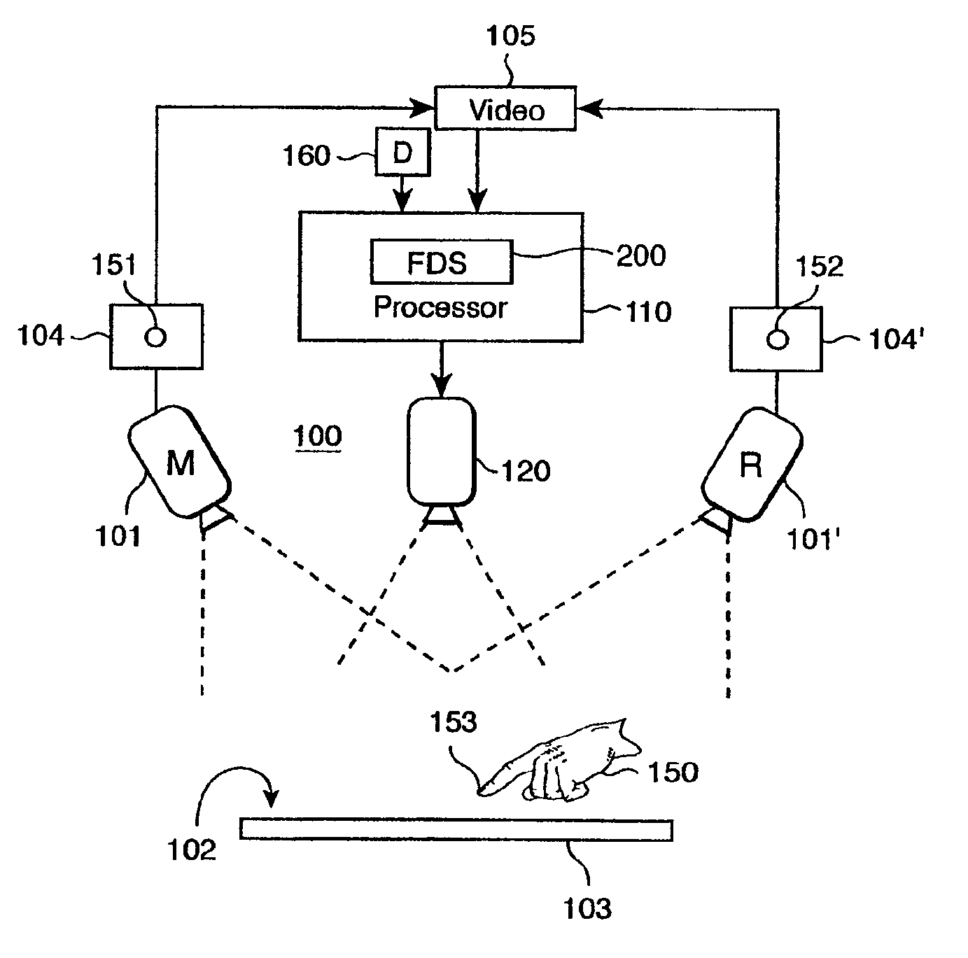
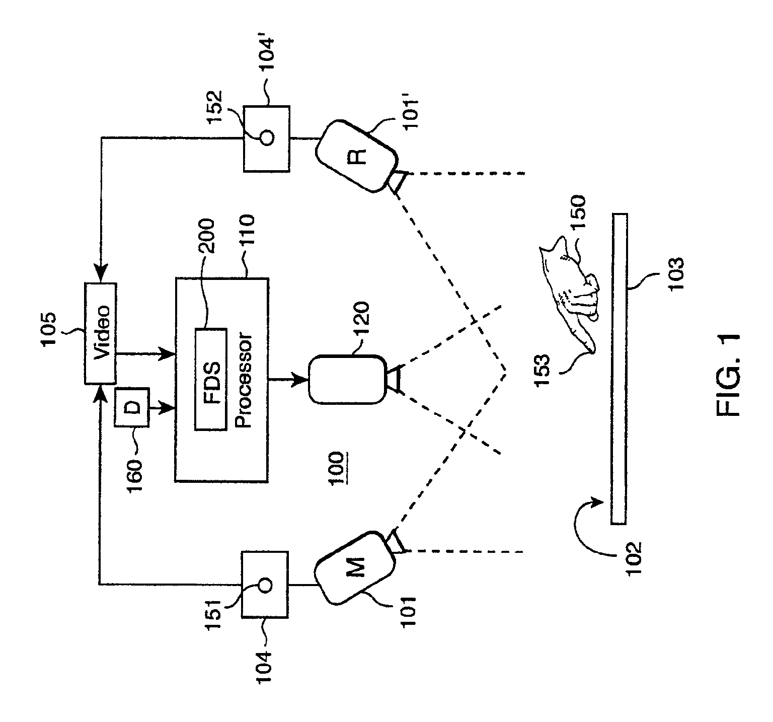
[0026]FIG. 1 shows a depth segmentation system 100 according to our invention. Our system 100 includes a pair of stereo cameras 101-101′, respectively a main camera M, and a reference camera R, aimed at a scene 102. The scene 102 includes a background object 103, for example, a table top or a game-board, and a foreground object 150, for example, a pointer or a game piece. The cameras 101-101′ acquire pairs of images 104-104′ that form a stereo video 105. The video 105 is analyzed by a processor 110.

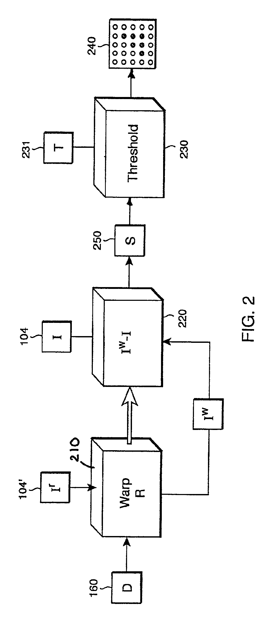
[0027]The processor 110 is substantially conventional, including a microprocessor, memory, and I / O interfaces and devices, coupled to each other. The microprocessor executes operating system programs, and application programs implementing a fast depth segmentation (FDS) method 200 according to our invention, as described in greater detail below with reference to FIG. 2. The system 100 can also include a projector 120 to illuminate the scene 102 with dynamically varying ima...


PUM


Abstract

The location of an object in a physical scene is identified with a stereo camera. A virtual surface is identified in the physical scene, and an approximate disparity set is constructed for the virtual surface. A main and a reference image of the scene are acquired by the stereo camera. The reference image is warped according to the disparity set, and subtracted from the main image to determine a set of depth residual values. Pixels having a substantially non-zero residual are identified with a surface of the object not coincident with the virtual surface.

Description

[0001]This application claims the benefit of Provisional Application No. 60 / 313,172, filed Aug. 17, 2001.FIELD OF THE INVENTION[0002]The present invention relates generally to the field of video analysis, and more particularly to segmenting depths in scenes observed by stereo video cameras.BACKGROUND OF THE INVENTION[0003]The increasing availability of inexpensive video cameras and high-quality projection displays is providing opportunities for developing novel interfaces that use computer vision. These interfaces enable interactive applications that impose little constraint on a user and the environment. For example, the user can interact with objects in a scene without the need for a physical coupling between the user, the objects, and a computer system, as in more conventional mouse, or touch-based computer interfaces.[0004]However, computer vision systems, with rare exceptions, are difficult to implement for applications where the visual appearance of objects and the scene chang...

Claims


Application Information

Patent Timeline
IPC IPC(8): H04N13/00H04N13/239
CPCG06T7/0075G06T7/0081G06T7/2033H04N13/0011G06T2207/20144H04N13/0239H04N13/0246H04N13/0253H04N13/0257H04N13/0285H04N13/0422H04N13/0459H04N2013/0081H04N2013/0092G06T2207/10012H04N13/0037G06T7/593G06T7/11G06T7/246G06T7/194H04N13/254H04N13/324H04N13/246H04N13/111H04N13/257H04N13/363H04N13/286H04N13/15H04N13/239
Inventor IVANOV, YURI A.PENTLAND, ALEX P.WREN, CHRISTOPHER R.
Owner MITSUBISHI ELECTRIC RES LAB INC
Why Eureka
Try Eureka