
Display device for displaying digital input image data using different filter segments for the lower and higher order bits

Inactive Publication Date: 2005-06-28
RAKUTEN INC
View PDF17 Cites 15 Cited by
  • Summary
  • Abstract
  • Description
  • Claims
  • Application Information

AI Technical Summary

Benefits of technology

[0037]It is an object of the present invention to provide a display device which is capable of representing gray levels more than the number of gray levels limited by the minimum switching time at which a light valve is turned ON and OFF and which suffers almost no brightness decrease.
[0039]Some gray levels have been heretofore impossible to display due to restrictions imposed by the minimum switching time at which the light valve is turned ON and OFF. Information about only visually sensitive brightness levels is reproduced using the light-transmitting filter corresponding to white light. Hence, smoother gray-scale representation can be accomplished without deteriorating the brightness.

Problems solved by technology

Some gray levels have been heretofore impossible to display due to restrictions imposed by the minimum switching time at which the light valve is turned ON and OFF.

Method used


Image

  • Display device for displaying digital input image data using different filter segments for the lower and higher order bits
  • Display device for displaying digital input image data using different filter segments for the lower and higher order bits
  • Display device for displaying digital input image data using different filter segments for the lower and higher order bits

Examples


first embodiment

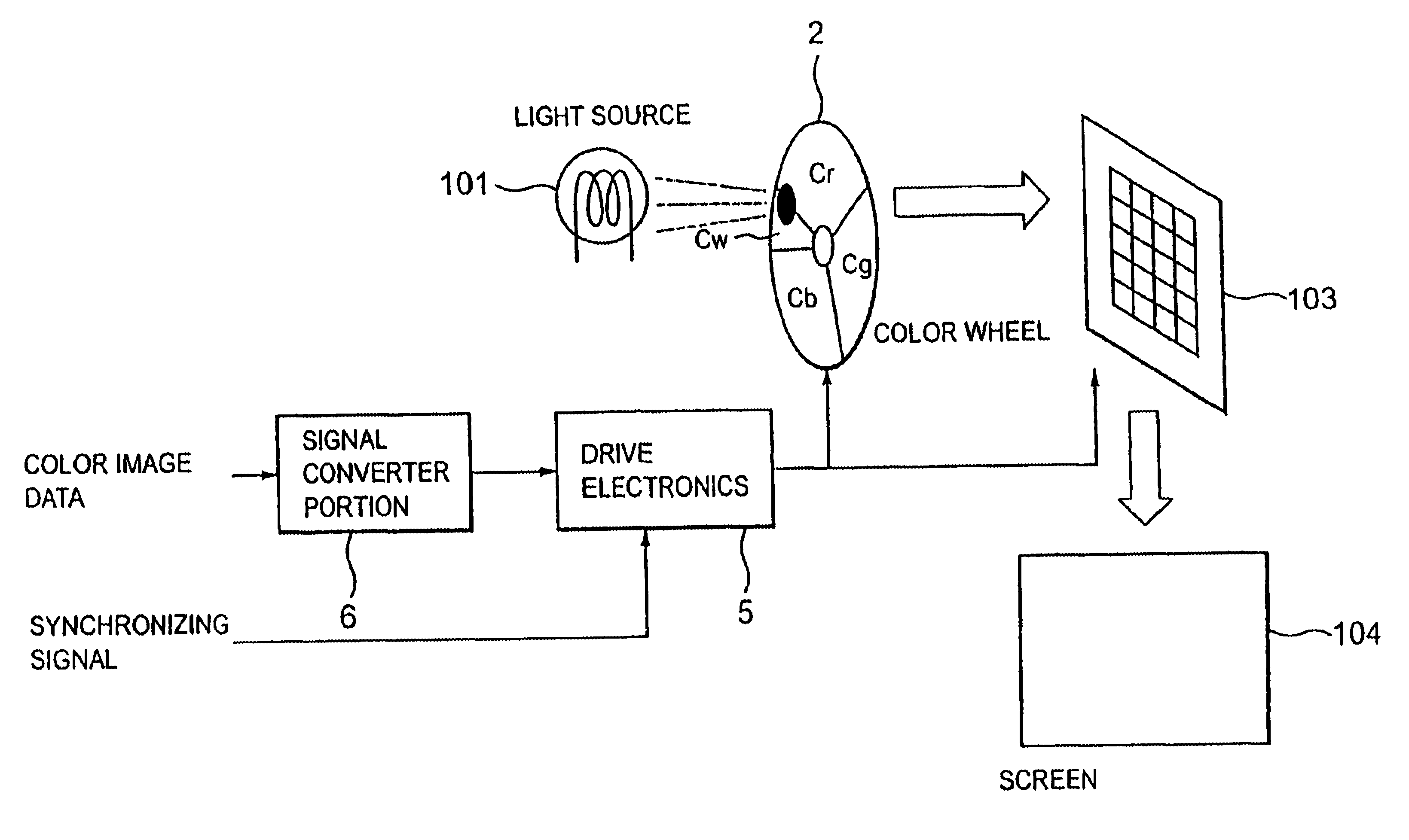
[0046]Referring to FIG. 3, there is shown a block diagram of a display device in accordance with the present invention. This display device comprises a light source 101, a color wheel 2, a light valve 103, a screen 104, a signal converter portion 6, and drive electronics 5.

[0047]As shown in FIG. 3, the color wheel 2 is divided into 4 segments including color filters Cr, Cg and Cb that transmit R, G, and B, respectively. The color wheel 2 further includes a color filter Cw such as a neutral density filter that transmits white light. This filter Cw shows almost flat spectral characteristics, as opposed to the filters Cr, Cg, and Cb. Let the color filters Cr, Cg, Cb, and Cw have transmissivities of fr(λ), fg(λ), fb(λ), and fw(λ), respectively fw(λ) is so set as to satisfy Eq. (1) below: ∫380780⁢fw⁡(λ)·V⁡(λ)⁢ ⁢ⅆλ=18·∫380780⁢{fr⁡(λ)+fg⁡(λ)+fb⁡(λ)}⁢V⁡(λ)⁢ⅆλ(1)

where (λ) is the wavelength of light, V(λ) is the relative spectral sensitivity characteristic of the human eye, and 1 / K is a coeff...

second embodiment

[0067]In the first embodiment, the color filter Cw is used from the first to the 1024th gray level. It is not necessary to use the color filter Cw for all the gray levels. The filter Cw may be employed only for dark image portions. An example of operation in this case is next described by referring to FIGS. 6(a)-6(d). FIG. 6(a) shows an image signal applied to the signal converter portion 6. FIG. 6(b) shows the brightness of an image reproduced by the color filters Cr, Cg, and Cb, and is the same as obtained in the first embodiment. FIG. 6(c) shows the brightness of an image reproduced by the color filter Cw. This filter Cw is used for only the 15th gray level and below. The filter Cw is kept OFF in response to the 16th gray level and above. The resultant brightness of the color filters Cr, Cg, Cb, and Cw is shown in FIG. 6(d).

[0068]The human eye's capability to discriminate bright portions is lower than the human eye's capability to discriminate dark portions. Therefore, where the ...

third embodiment

[0069]In the first and second embodiments, 10 bits of image data are separated into the upper-order 7 bits and the lower-order 3 bits and displayed. The present invention is not limited to this separation method. For example, (n+m)-bit image data (where n and m are any arbitrary numbers equal to or greater than 0) may be divided into the upper-order n bits and the lower-order m bits and displayed. It is only necessary that the upper-order n bits and the lower-order m bits suitable for the characteristics of the display device be established.


PUM


Abstract

There is disclosed a display device using a color wheel having a color filter Cw, in addition to normal color filters corresponding to the three primary colors. The filter Cw has almost flat spectral transmission characteristics. Brightness information included in a color image signal is quantized with (n+m) bits. Information corresponding to the lower-order n bits is displayed by light transmitted through the filter Cw. Information corresponding to the upper-order n bits is displayed by light transmitted through the normal color filters. Only brightness information to which the human eye is visually sensitive is reproduced by the filter Cw having a lower transmissivity. This can eliminate a lack of the number of gray levels due to a constraint on the minimum switching speed of a light valve. Furthermore, the brightness little deteriorates.

Description

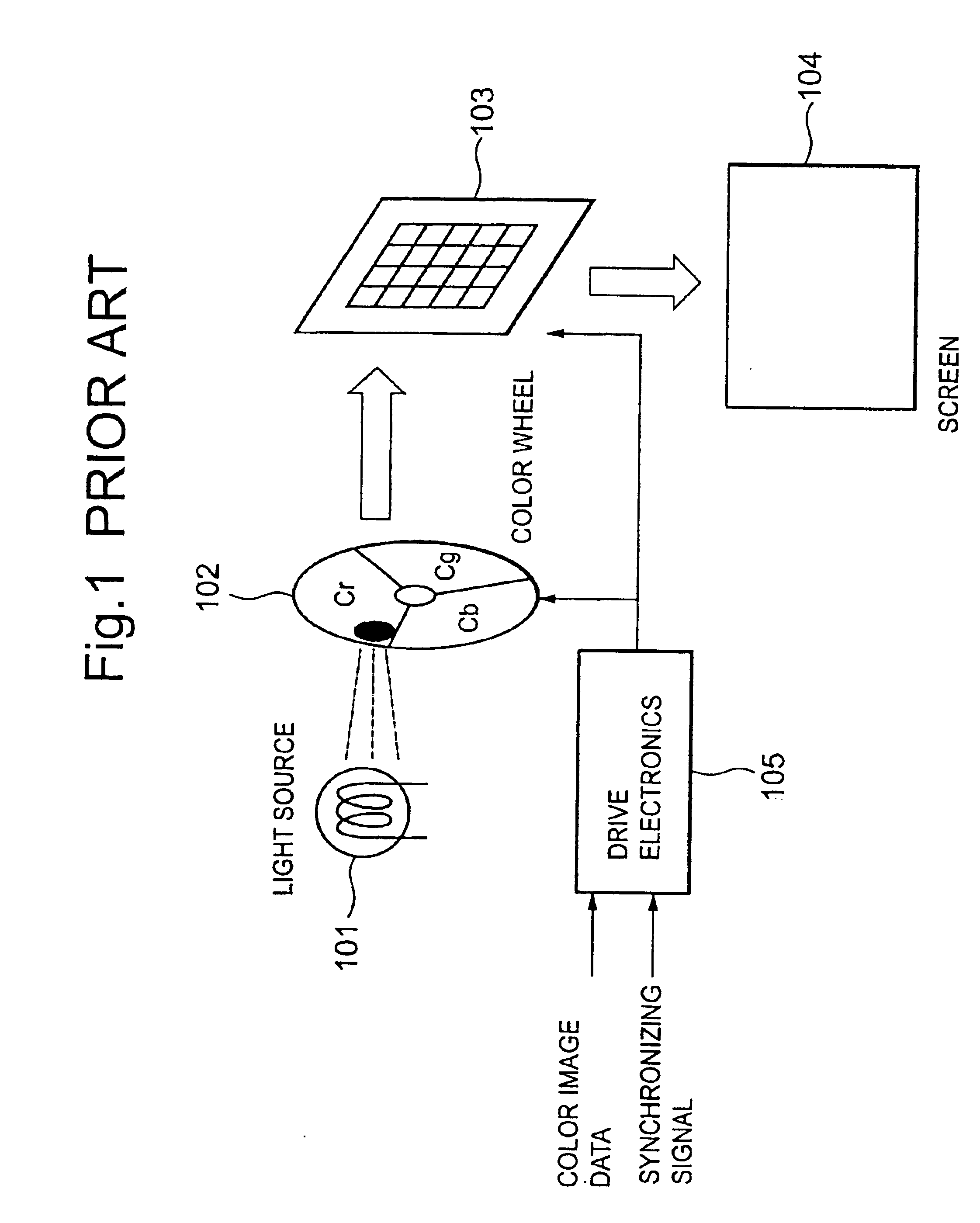
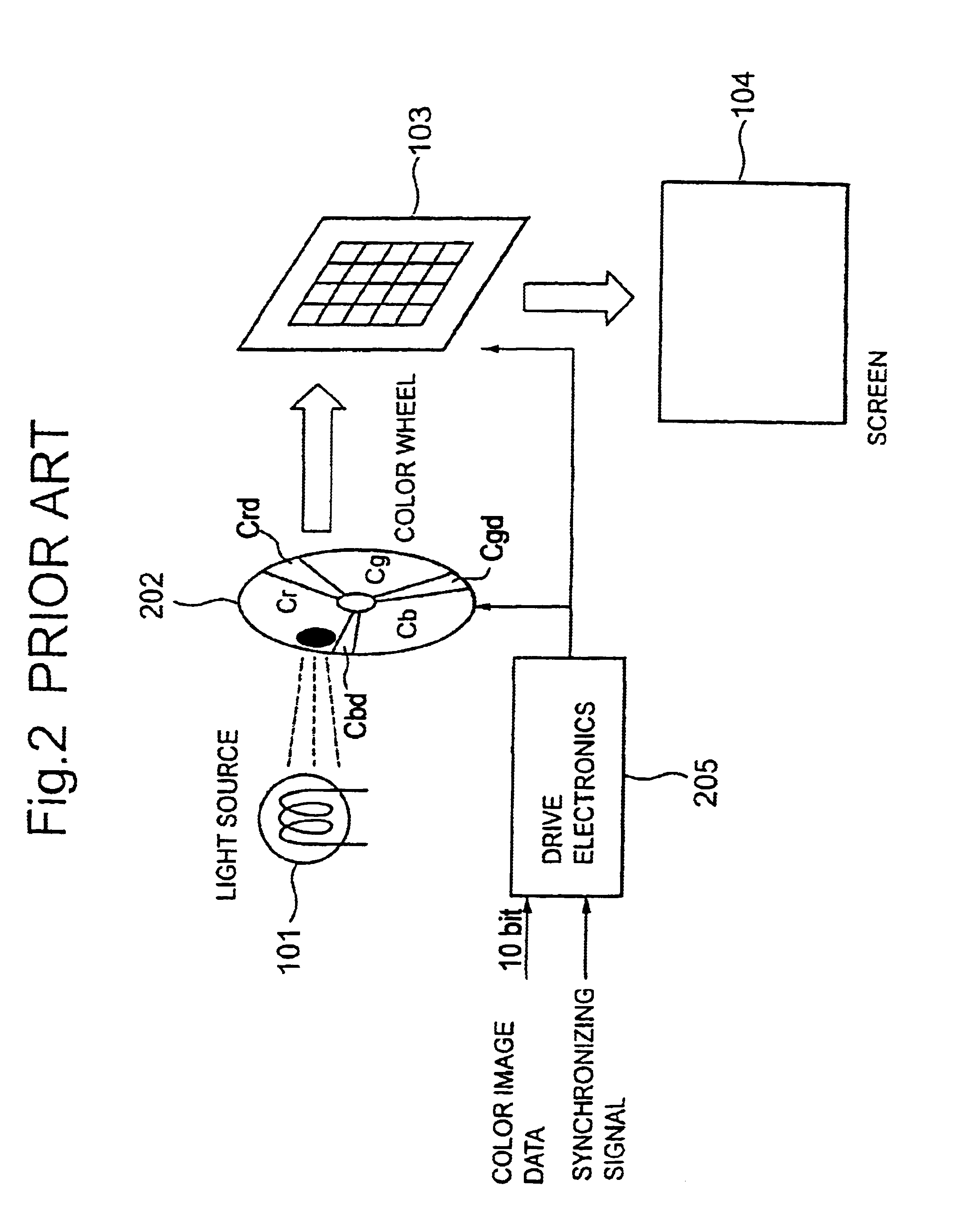
BACKGROUND OF THE INVENTION[0001]1. Field of the Invention[0002]The present invention relates to a display device and, more particularly, to a display device using color filters to reproduce colors.[0003]2. Description of the Prior Art[0004]In recent years, numerous display devices have been available in which color filters are used to decompose light from a light source into N colors that are projected onto a screen for reproducing a color image, where N is a positive integer. Normally, N=3, and light is decomposed into red (R), green (G), and blue (B) colors which are projected to reproduce a color image. The simplest example of implementation for achieving this is given below.[0005]FIG. 1 shows an example of a display device, comprising a light source 101, a color wheel 102, a light valve 103, a screen 104, and drive electronics 105. The display device shown in FIG. 1 is assumed to project light decomposed into R, G, and B colors, thus reproducing color images.[0006]The operation...

Claims


Application Information

Patent Timeline
IPC IPC(8): G09G3/34G09G5/02G02B5/20G03B21/00G09F9/00H04N5/74G09G3/20H04N9/31
CPCG09G3/3413G09G3/2077G09G2340/0428G09G2310/0235G09G5/02
Inventor MINAMI, KOJISUZUKI, YOSHITERUTERAMOTO, KOHEISUGIURA, HIROAKISHIKAMA, SHINSUKE
Owner RAKUTEN INC
Learn More