Method of determining physical properties of an optical layer or layer system

a technology of optical layer and layer system, applied in the direction of optical radiation measurement, vacuum evaporation coating, instruments, etc., can solve the problem of a considerable amount of time and effort that is not practicabl

Inactive Publication Date: 2006-01-12
APPLIED MATERIALS GMBH & CO KG
View PDF8 Cites 17 Cited by
  • Summary
  • Abstract
  • Description
  • Claims
  • Application Information

AI Technical Summary

Benefits of technology

[0017] In accordance with a further advantageous embodiment, the nonlinear optimization for estimating the layer thickness is, moreover, modified in that a series of starting or initial values is used for the layer thickness. During optimization, this determines not only a minimum of that evaluation function which belongs to the nonlinear optimization algorithm, but also a separate minimum value for each starting or initial value, the smallest value then being cho

Problems solved by technology

For this purpose, large substrates, such as architectural glazing, will require, for example, 2,000 measuring points spread across the subst

Method used


Image

  • Method of determining physical properties of an optical layer or layer system
  • Method of determining physical properties of an optical layer or layer system
  • Method of determining physical properties of an optical layer or layer system

Examples


Embodiment Construction

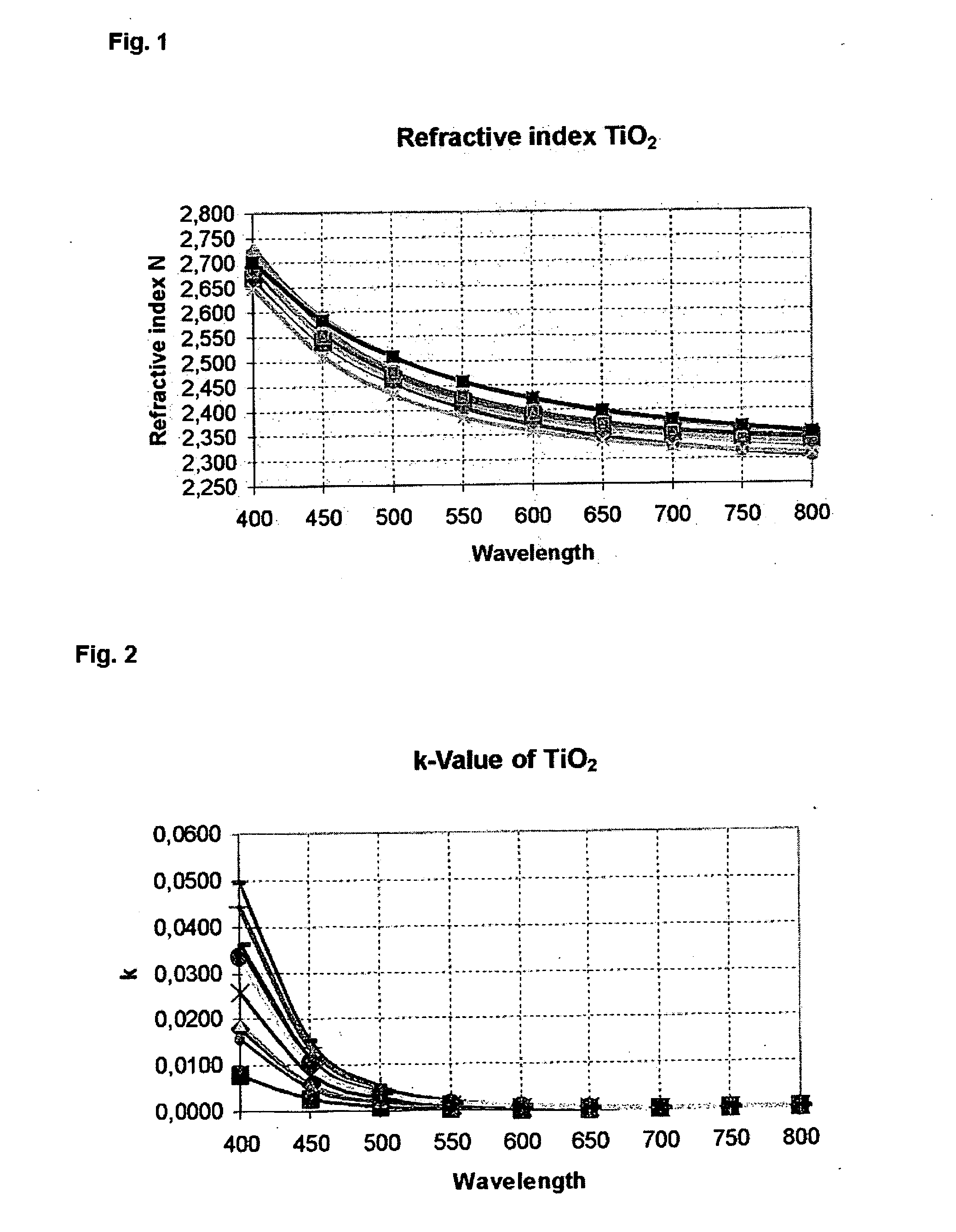
[0023]FIG. 1 depicts a diagram that illustrates the refractive index n as a function of the wavelength of the light used for a TiO2 layer. The different curves are recorded for TiO2 layers which were deposited under varying coating conditions with a different oxygen content in the coating atmosphere. It can be gathered from the various curves that the refractive index n, as a function of the coating conditions, is varied by an additive constant, the extent of variation being determined by the prevalent coating conditions in each case.

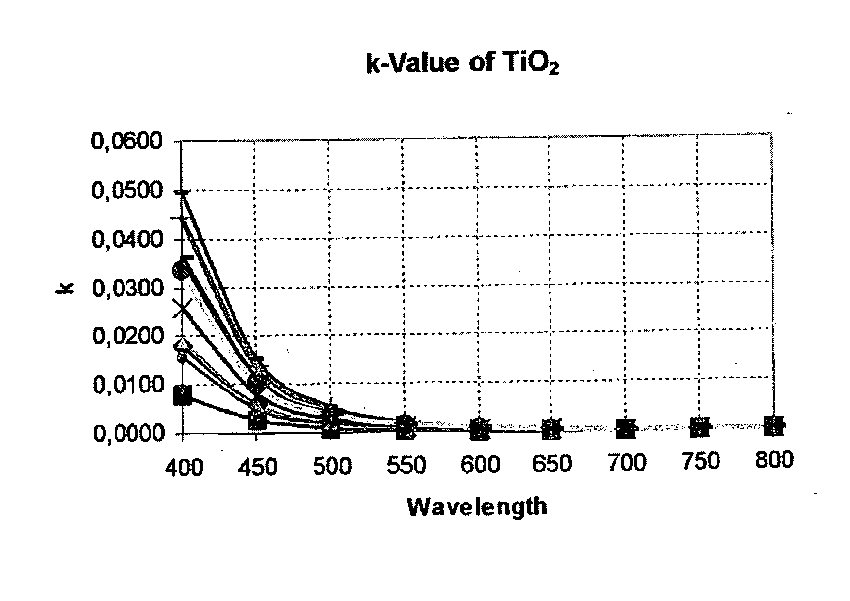
[0024] In the same way, FIG. 2 depicts the extinction coefficient k for various TiO2 layers as a function of the wavelength of the light used. Here, too, the oxygen-induced variation in extinction coefficient for the variously deposited TiO2 layers can be described by an additive constant at least in the range below a wavelength of 600 nm.

[0025] The variation in both refractive index n and extinction coefficient k, which variation is caused by differe...


PUM

PropertyMeasurementUnit
Thicknessaaaaaaaaaa
Transmissionaaaaaaaaaa
Surface areaaaaaaaaaaa

Abstract

The present invention relates to a method of determining physical properties of an optical layer or layer system by means of spectral transmission and/or reflection measurements, whereby in accordance with the spectrum of the transmission and/or reflection measurement, reference values for the wavelength-dependent refractive indices n0 and/or extinction coefficients k0 are chosen from known values or are determined experimentally and the variation that characterizes the layer is described by wavelength-independent variation constants Kn and Kk for the refractive indices and extinction coefficients.

Description

[0001] This application claims priority, pursuant to 35 USC § 119, to European Patent Application No. 04021243, filed Sep. 7, 2004, which is incorporated in is entirety by reference herein. FIELD OF THE INVENTION [0002] The present invention relates to a method of determining physical properties of an optical layer or layer system with a transmission and / or reflection measurement. BACKGROUND OF THE INVENTION [0003] The coating of substrates, particularly glass substrates that have optically effective layers, is wide spread. Examples include so-called low-E or thermal insulation layers for architectural glazing, antireflective layers such as for VDUs and the like. Such layers are deposited for example by sputtering techniques under vacuum conditions, it being preferable, for economic reasons, to use substrates which cover a large surface area. [0004] In this regard, it is important that the quality of the deposited layers can be checked so as to ensure that the desired physical prope...

Claims


Application Information

Patent Timeline
IPC IPC(8): G01N21/41G01B11/28G01B11/06
CPCG01B11/0625G01N21/8422G01N21/41C23C14/044
Inventor LOTZ, HANS-GEORGSCHROEDER, JURGEN
Owner APPLIED MATERIALS GMBH & CO KG
Why Eureka
Try Eureka