Door rail system

Inactive Publication Date: 2005-07-05
C R LAURENCE
View PDF26 Cites 43 Cited by
  • Summary
  • Abstract
  • Description
  • Claims
  • Application Information

AI Technical Summary

Benefits of technology

[0019](8) to provide a rail system that is easier to assemble and disassemble because of easy accessibility of fastening members (e.g., screw heads);
[0020](9) to provide

Problems solved by technology

One potential problem with the door rail system of described U.S. Pat. No. 5,069,010 is that the hole in the side of the rail caused by access port 56 is not considered aesthetically appropriate for many applications.
While it is necessary to cover the sides of the rail with some type of cladding, such as an aluminum plate, this adds expense, and makes the rail system more difficult to assemble and disassemble.
Another potential problem with the rail system of U.S. Pat. No. 5,069,010 is that accessory channel s

Method used


Image

  • Door rail system
  • Door rail system
  • Door rail system

Examples


second embodiment

[0068]FIG. 12 shows a rail system 200 according to the present invention. Rail system 200 includes housing 202, clamp member 204 and screw 206. As screw 206 is tightened, it forces clamp member 204 to move generally in the driven direction of arrow A. Because housing 202 and clamp member 204 are in contact at surfaces inclined with respect to the screw-tightening direction A, this causes the arms 208, 210 of clamp member 204 to move toward each other (in the clamping directions respectively shown by arrows B and C) to provide clamping force on a pane (not shown). It is noted that this embodiment uses a unitary clamp member 204 that flexes to provide the clamping force, and that the driven direction is oriented toward the pane, rather than away from it (as seen in the FIG. 2 embodiment).

third embodiment

[0069]FIG. 13 shows a rail system 300. While rail system 300 is not a preferred embodiment, it does serve to illustrate some of the breadth of variation possible in effecting clamping by uses of inclined surfaces according to the present invention. Rail system 300 includes housing 302, first clamp member 304a, second clamp member 304b and screw 306. Screw 306 is tightened to force nut strip 308 in the driven direction indicated by arrow D. This in turn forces clamp members 304 to move in driven direction D.

[0070]When first clamp member 304a moves in driven direction D, contact between its inclined surface 322 and roller 324 (which is built into housing 302) forces first clamp member 304a to move by translation and / or rotation in the clamping direction of arrow E to clamp down on a pane (not shown). While the roller 324 would add expense and potential structural weakness, it could potentially: (1) reduce wear on housing 302 and clamp member 304a; and (2) guide an irregular and / or cur...

first embodiment

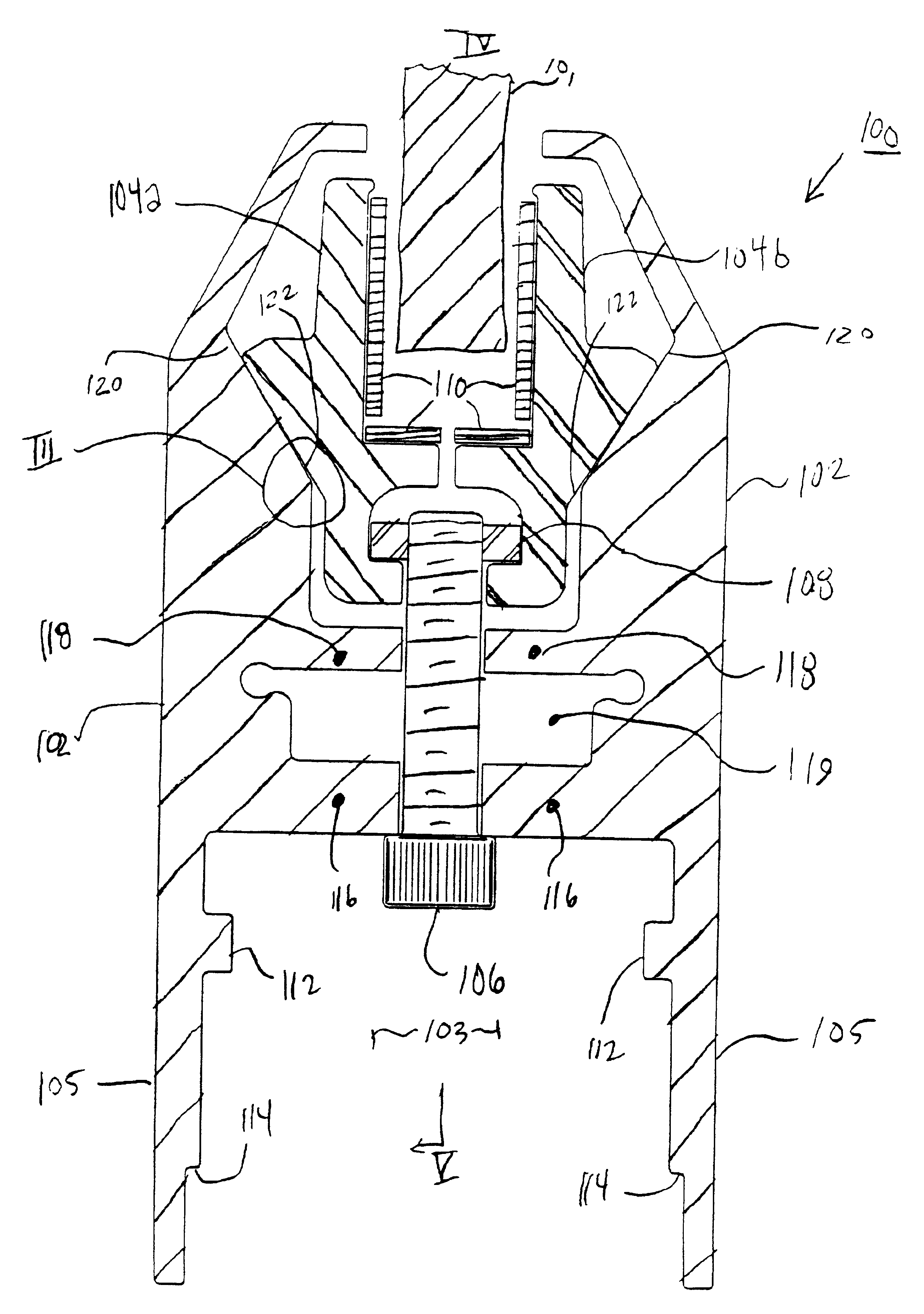
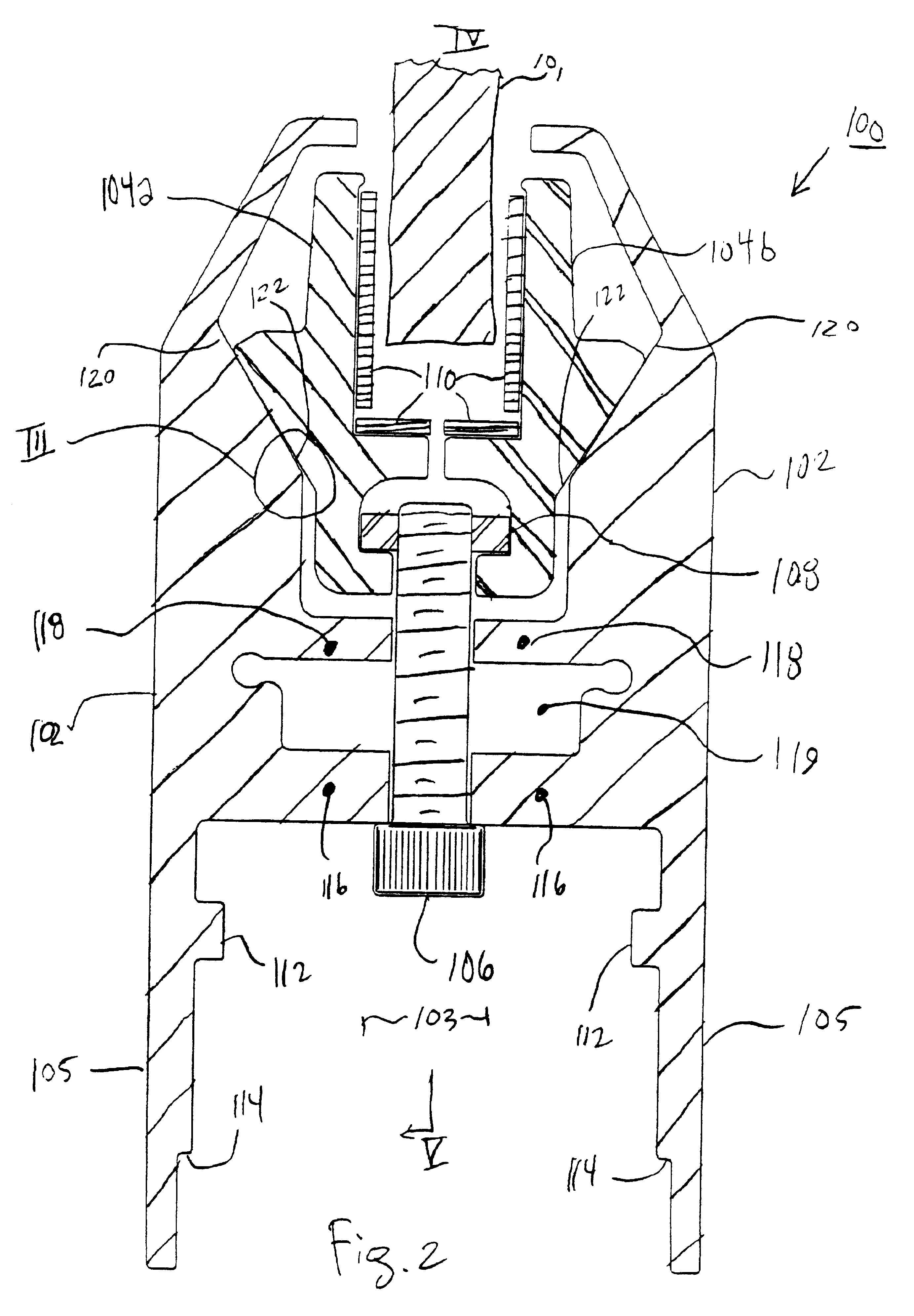
[0072]Now that some possible variations have been explored, the focus will return to FIGS. 2 and 3 so that some of the specific advantages of this preferred embodiment can be explained. As shown in FIG. 2, mating, inclined surfaces 120 and 122 are close to parallel, but not exactly parallel. As shown in the magnified view of FIG. 3, inclined surface 120 is inclined at angle X from the horizontal direction, while inclined surface 122 is inclined at a slightly steeper angle Y from the horizontal. More particularly, angle X is preferably 59 degrees, while angle Y is preferably 60 degrees.

[0073]However, wide variation in angles X and angle Y, as well as in the difference between angle X and angle Y, are possible. Different choices for these angles and for the difference between these angles can be used to optimize: (1) the correlation between driving torque of screw 106 and clamping force; and (2) the distribution of clamping force along pane 101.

[0074]One advantage of mating inclined s...


PUM


Abstract

A rail system for holding a panel, such as a plate glass pane, in a door and/or wall partition. The rail system includes a housing and a clamp member having a wedging geometry so that when the clamp member is actuated with respect to the housing in a first direction, at least a portion of the clamp member will move in a clamping direction, which is different than the first direction to clamp the panel.

Description

REFERENCE TO RELATED APPLICATIONS[0001]This application is a divisional of U.S. patent application Ser. No. 09 / 631,148, now U.S. Pat. No. 6,434,905, filed Aug. 2, 2000 and titled DOOR RAIL SYSTEM.BACKGROUND OF THE INVENTION[0002]Rail systems are conventionally used to hold plate glass panels or panes (or other transparent, translucent or opaque panels) in a doorway opening or for use as a wall partition. Usually, the rail system runs along one or more edges of the panel and secures the panel at its edges. Preferably, the rail system includes an accessory channel space to hold miscellaneous door frame hardware, such as locking hardware, pivots and hardware related to hydraulic closure devices.[0003]In many prior art rail systems, such as those typically used in the doors of shopping malls, the rail is permanently attached to the pane. Of course, this makes it difficult or impossible to remove the rail from the pane, and this is generally considered to be a disadvantage of these perma...

Claims


Application Information

Patent Timeline
IPC IPC(8): E06B3/02E06B3/54E06B3/58
CPCE06B3/02E06B3/5454E06B3/5864
Inventor SPRAGUE, GARY
Owner C R LAURENCE
Why Eureka
Try Eureka