Composite decking system

Inactive Publication Date: 2005-07-05
ZELLCOMP LLC
View PDF12 Cites 18 Cited by
  • Summary
  • Abstract
  • Description
  • Claims
  • Application Information

AI Technical Summary

Benefits of technology

[0007]The open channel configuration of the baseplate of the present invention allows for easy access within the channels of the base section, and therefore the sides of the ribs, thereby simpli

Problems solved by technology

While the construction techniques, and materials employed, have evolved over time for steel and/or concrete bridges, the construction process has proved to be very labor intensive, and the resulting structures have proven susceptible to corrosion and other degradations.
While the patent indicates that the tube may be made using a pultrusion process, the actual fabrication of such tubes using pultrusion has proven difficult, primarily because pultrusion of hollow tubes, with a fully enclosed passage, is technologically difficult.
In s

Method used


Image

  • Composite decking system
  • Composite decking system
  • Composite decking system

Examples


Example

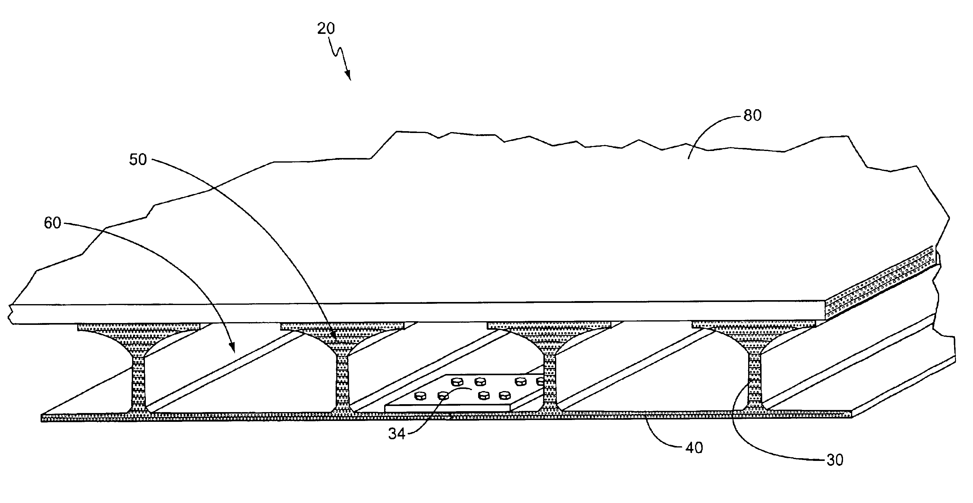
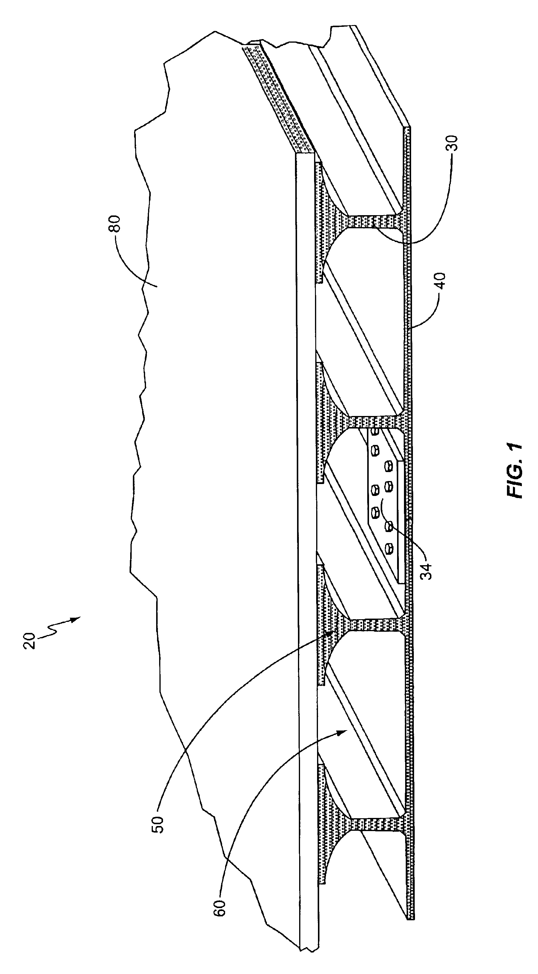
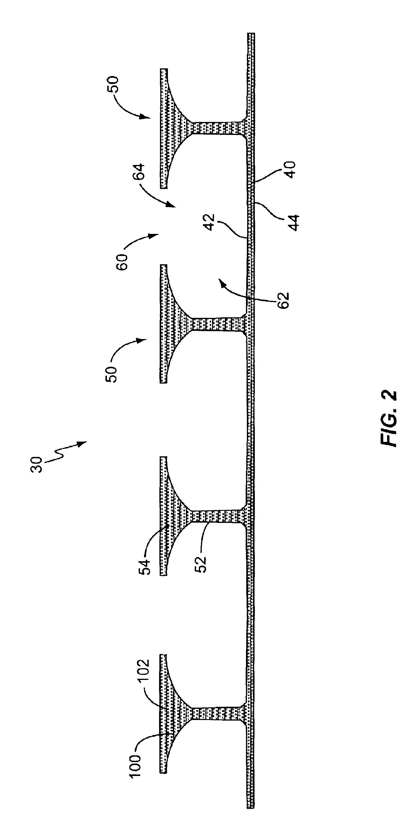
[0012]One embodiment of a composite structural assembly of the present invention is shown in FIG. 1, and generally indicated at 20. The assembly 20 includes a baseplate 30 and a top plate 80 secured to the baseplate 30. As shown in more detail in FIGS. 2-3, the baseplate 30 includes a base section 40, a plurality of ribs 50, and a plurality of channels 60. The base section 40 may be a generally flat, preferably rectangular, member with a top side 42 and a bottom side 44. The ribs 50 extend up from the top side 42 of the base section 40 and may advantageously be of a generally T-shaped configuration with a column section 52 and a cap section 54. The column section 52 extends generally perpendicularly away from the base section 40 and may have a generally rectangular cross-section, or tapered as desired. The joint between the column section 52 and the top side 42 of the base section 40 may be configured to reduce stresses and / or to simplify manufacturing, such as by being appropriatel...


PUM

PropertyMeasurementUnit
Widthaaaaaaaaaa
Lengthaaaaaaaaaa
Lightaaaaaaaaaa

Abstract

A composite deck assembly includes a baseplate and a top plate secured to the baseplate. The baseplate is formed from a first composite matrix comprising strands of reinforcing fibers oriented in first direction and a polymer resin. The baseplate includes a plurality of ribs and a plurality of laterally extending open channels disposed between the ribs. The top plate is formed from a second composite matrix of reinforcing fibers in a polymer resin, and is secured, optionally releasably, to the baseplate so as to generally enclose at least a portion of the channels. All the reinforcing fibers in the baseplate may be limited to being either the strands oriented in the first direction or matted reinforcing fibers having a random orientation. At least one of the base section and the top plate may be translucent. The open channel configuration simplifies manufacture and lowers cost.

Description

BACKGROUND OF THE INVENTION[0001]The present invention is directed to a structural assembly, formed primarily from composite matrix materials having reinforcing fibers in a polymer matrix, which may be used as a decking system or for other applications.[0002]The need for alternative materials and configurations for load bearing decks has long been recognized. Conventional load bearing decks, such as for vehicular bridges, have historically been made from steel and concrete. While the construction techniques, and materials employed, have evolved over time for steel and / or concrete bridges, the construction process has proved to be very labor intensive, and the resulting structures have proven susceptible to corrosion and other degradations.[0003]Partially in response to these cost and degradation issues, it has been proposed to use decking systems based on polymer composite matrix materials rather than steel and / or concrete. For instance, U.S. Pat. No. 5,794,402, incorporated herein ...

Claims


Application Information

Patent Timeline
IPC IPC(8): E01D19/12E04B5/02E04B5/10E04B5/46E04C3/28
CPCB32B3/20B32B27/04E01D19/125E04B5/026E04B5/46E04C3/28E04B5/023E01D2101/40Y10T428/2457Y10T428/249924
Inventor RICHARDS, DANIEL H.
Owner ZELLCOMP LLC
Why Eureka
Try Eureka