System and method for communicating over power terminals in DC tools

Inactive Publication Date: 2005-07-05
BLACK & DECKER INC
View PDF30 Cites 162 Cited by
  • Summary
  • Abstract
  • Description
  • Claims
  • Application Information

AI Technical Summary

Problems solved by technology

Along with an increase in the type of cordless power tools has come an increase in technical complexity of the cordless power tools.
Known methods of communicating with cordless power tools to extrac

Method used


Image

  • System and method for communicating over power terminals in DC tools
  • System and method for communicating over power terminals in DC tools
  • System and method for communicating over power terminals in DC tools

Examples


Embodiment Construction

[0018]The following description of the preferred embodiments is merely exemplary in nature and is in no way intended to limit the invention, its application or uses.

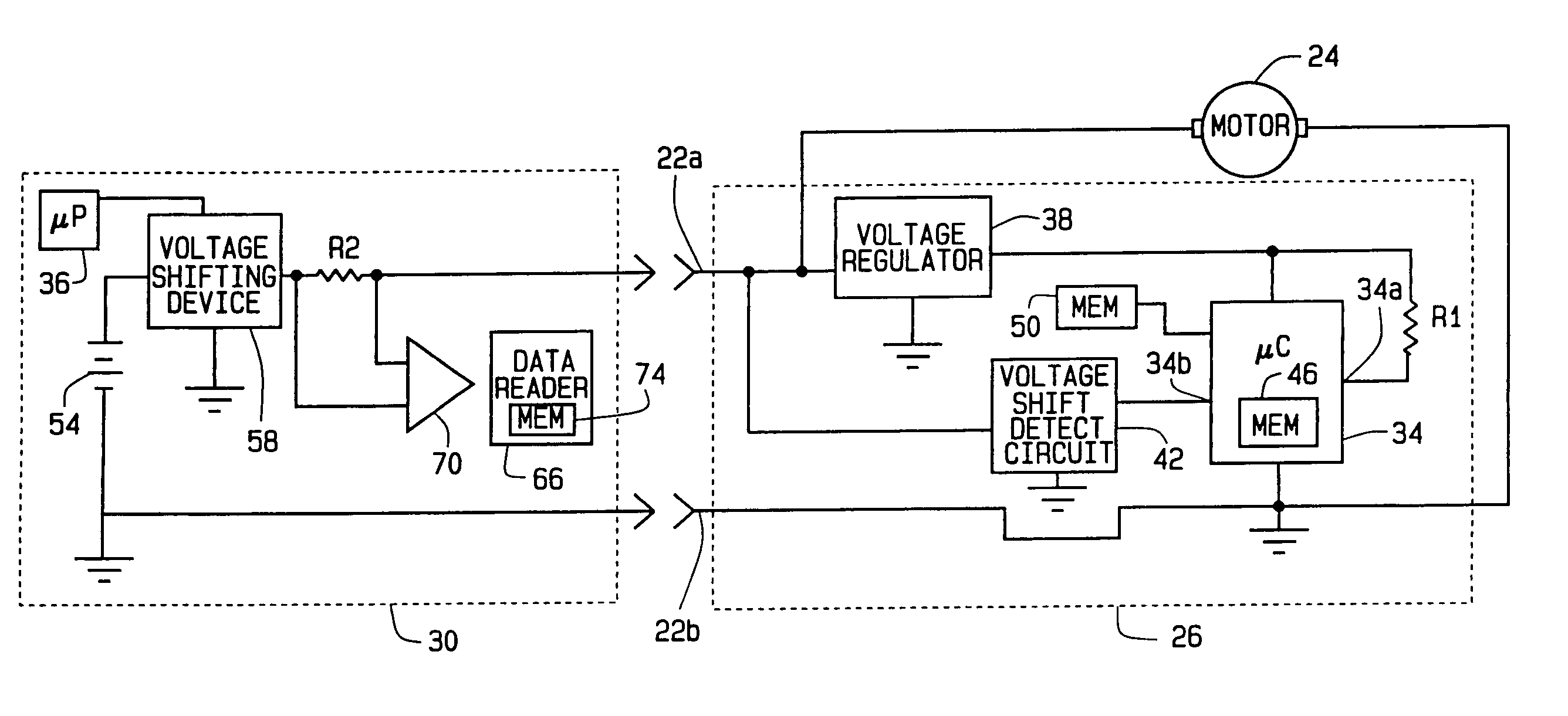
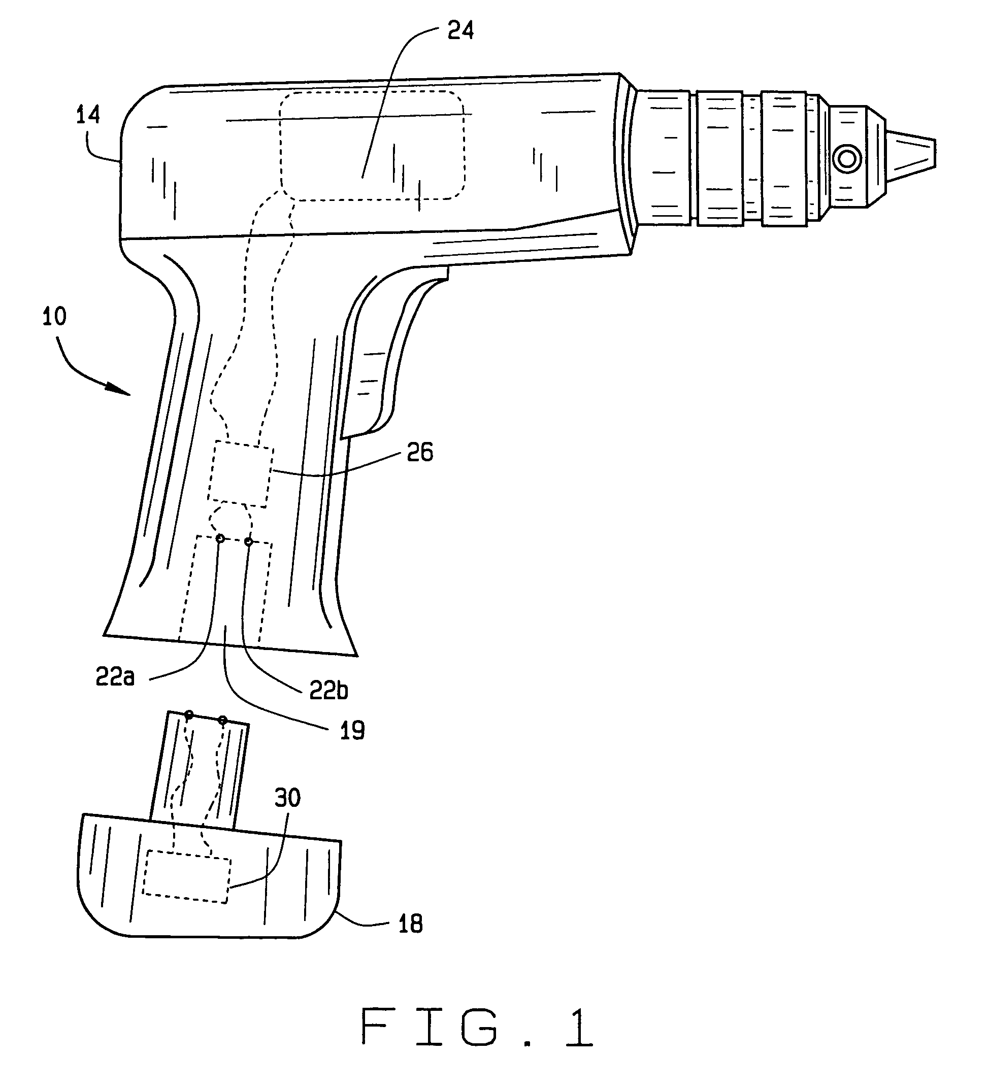
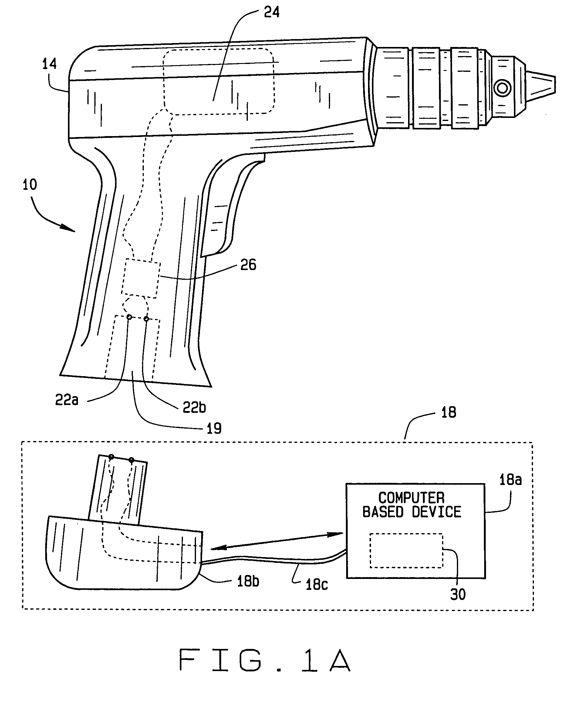
[0019]FIG. 1 is a simplified block diagram of a system 10 for communicating data to and / or from a cordless power tool 14, in accordance with a preferred embodiment of the present invention. It will be appreciated that although the cordless tool 14 is shown in FIG. 1 as a cordless drill, the power tool 14 can be any cordless tool such as a nailer, drill, screwdriver, circular saw, reciprocating saw, scroll saw or sander, etc. The system 10 includes a data transfer device 18, also referred to as a host device that is adapted to connect to power terminals 22a and 22b of the power tool 14 to communicate with the power tool 14 when power tool 14 is in a communications mode. The power terminals 22a and 22b are also used for connecting a tool power supply, such as a removable, portable battery pack, to the tool 14 to provide po...


PUM

PropertyMeasurementUnit
Poweraaaaaaaaaa
Transmissionaaaaaaaaaa
Electric potential / voltageaaaaaaaaaa

Abstract

A system and method for unidirectionally or bi-directionally communicating information and data to and from an electronic module housed within a cordless power tool, over power terminals of the cordless power tool, while a battery pack of the tool is removed from the tool. A data transfer device is connected to at least one power terminal of the tool in place of the battery pack. The power terminal is also used for electrically connecting the battery pack to the tool during normal operation of the tool. A voltage supplied by the data transfer device to the tool is sequentially varied between a first level and a second level, in accordance with a predetermined communications protocol, to transmit data from electronic module of the tool to the data transfer device. A voltage signal applied to the electronic module of the tool is sequentially shifted between a first voltage and a second voltage to transmit data from the data transfer device to the tool. Thus, data can be transmitted between the tool and the data transfer device without requiring disassembly of the tool.

Description

CROSS-REFERENCE TO RELATED APPLICATIONS[0001]This application is a continuation of application Ser. No. 10 / 768,947, filed Jan. 30, 2004, now abandoned. The entire contents of the aforementioned patent application are incorporated herein by reference.FIELD OF THE INVENTION[0002]The present invention relates to cordless power tools. More specifically, the invention relates to communicating information between the power tool and a data transfer device via the power terminals of the tool. The power terminals are the same power terminals used for connecting to a tool power supply, i.e. a portable battery pack, during operation of the tool.BACKGROUND OF THE INVENTION[0003]Contemporary cordless power tools are becoming more common place in homes and on commercial construction job sites. The evolution of cordless power tools has resulted in a large variety of power tools being manufactured in cordless versions. For example, power tools such as nailers, drills, screwdrivers, circular saws, r...

Claims


Application Information

Patent Timeline
IPC IPC(8): B25B21/00
CPCB25B21/00B25B23/14B25F5/00
Inventor BROTTO, DANIELE C.FORSTER, MICHAEL KENNETH
Owner BLACK & DECKER INC
Why Eureka
Try Eureka