Hammer

a technology of electric hammer and hammer head, which is applied in the direction of manufacturing tools, percussive tools, portable drilling machines, etc., can solve the problems of difficult or impossible assembly of components within the increased internal diameter portion of the spindle, inability to provide axial stops against rearward movement within the spindle, and difficulty in correctly assembling into the hammer spindle. , to achieve the effect of reducing the number of components

Inactive Publication Date: 2005-07-05
BLACK & DECKER INC
View PDF11 Cites 36 Cited by
  • Summary
  • Abstract
  • Description
  • Claims
  • Application Information

AI Technical Summary

Benefits of technology

[0022]In a preferred design there are two peg elements, although there may be more than two peg elements. In some designs two or more

Problems solved by technology

Within a single spindle part the internal diameter of the spindle cannot increase and then decrease, as this would make it difficult or impossible to assemble components within the increased internal diameter portion of the spindle.
Thus, the annular shoulders are able to provide axial stops against forward movement of components within the spindle, but cannot provide axial stops against rearward movement within the spindle.
The problem with circlips is that they

Method used


Image

  • Hammer
  • Hammer
  • Hammer

Examples


Embodiment Construction

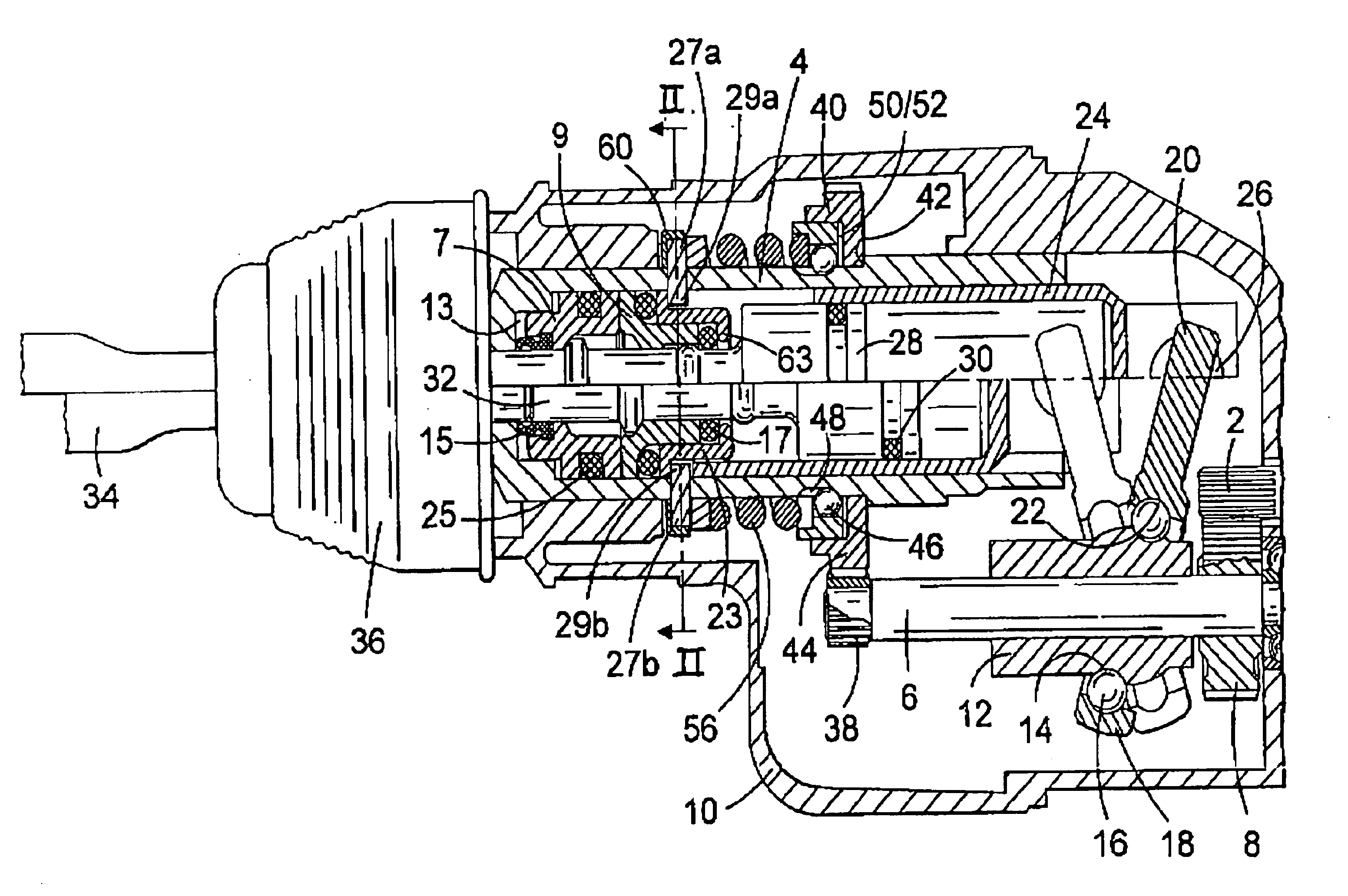
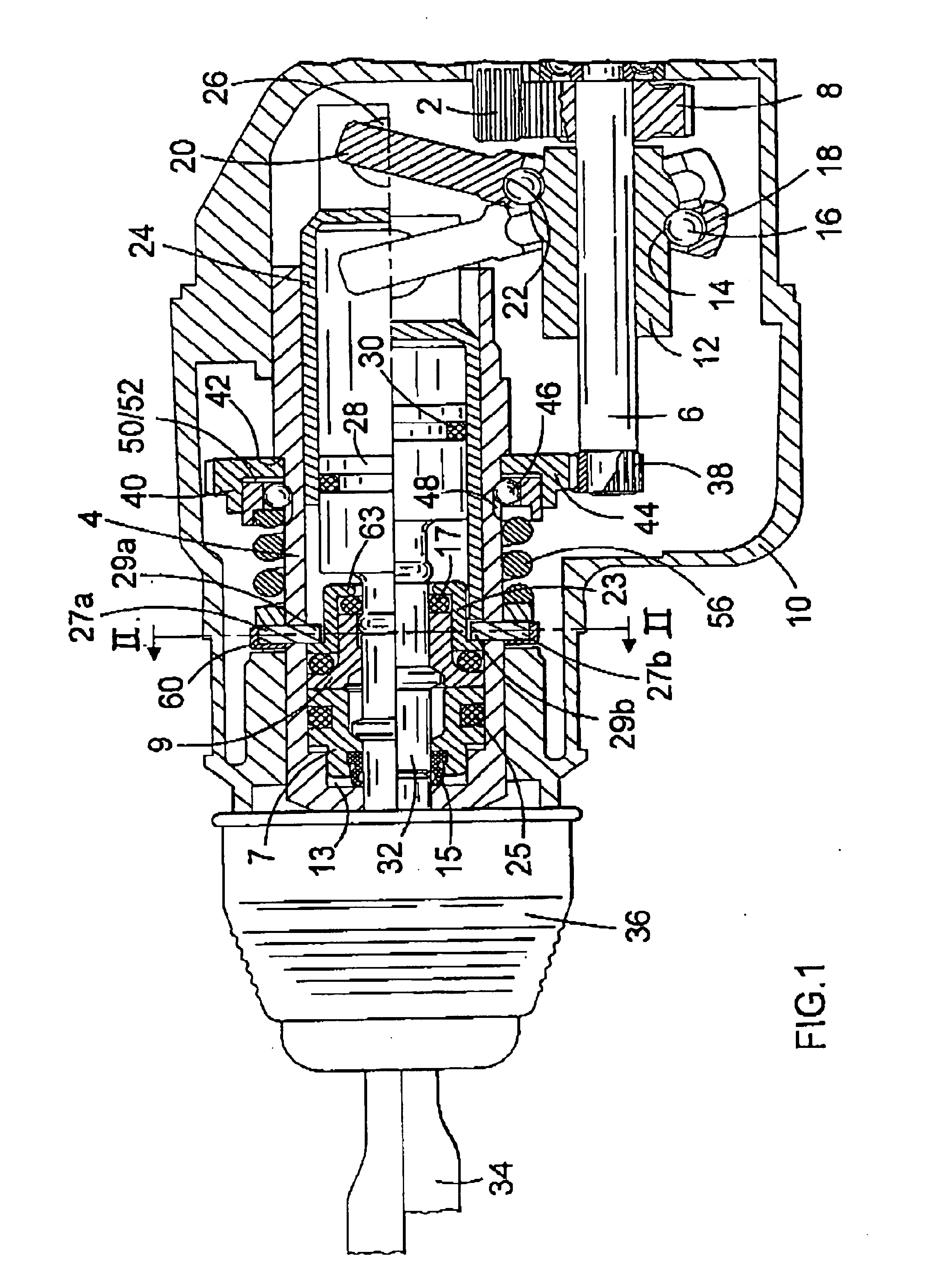
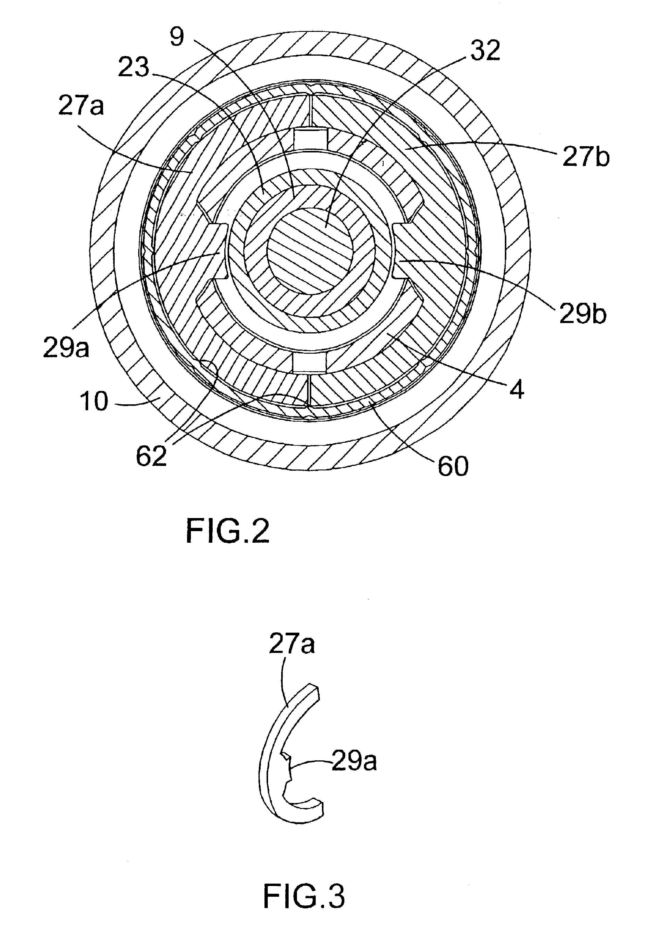
[0032]The rotary hammer has a forward portion which is shown in FIG. 1 and a rearward portion incorporating a motor and a rear handle, in the conventional way. The handle may be of the pistol grip or D-handle type. The handle portion incorporates a trigger switch for actuating the electric motor, which motor is formed at the forward end of its armature shaft with a pinion (2). The pinion (2) of the motor rotatingly drives an intermediate shaft (6) via a gear (8) which gear is press fit onto the rearward end of the intermediate shaft (6). The intermediate shaft is rotatingly mounted in a forward housing part (10) of the hammer in a conventional manner. In the FIG. 1 arrangement the longitudinal axis of the motor is parallel with the longitudinal axis of the hollow cylindrical spindle (4) of the hammer. Alternatively, the motor could be aligned with its axis perpendicular to the axis of the spindle (4), in which case a bevel pinion would be formed at the end of the armature shaft of t...


PUM

PropertyMeasurementUnit
Resilienceaaaaaaaaaa

Abstract

An electrically powered hammer comprising a hollow cylindrical spindle mounted within a housing. A portion of the spindle is formed with a plurality of circumferentially spaced holes and a corresponding number of peg elements are fitted to the spindle, such that each peg element extends through a corresponding hole in the spindle and radially inwardly of the internal surface of the spindle, in such a way that the peg elements together form an axial stop for one or more additional hammer components located within the spindle. Each peg element may alternatively or additonally extend radially outwardly of the corresponding hole in the spindle, in such a way that the peg elements together form an axial stop for one or more additional hammer components located around the spindle. The axial stops formed by the peg elements can replace circlips, which are generally used to form the axial stops.

Description

BACKGROUND OF INVENTION[0001]This invention relates to electric hammers having an air cushion hammering mechanism.[0002]Such hammers will normally have a housing and a hollow cylindrical spindle mounted in the housing. The spindle allows insertion of the shank of a tool or bit, for example a drill bit or a chisel bit, into the front end thereof so that it is retained in the front end of the spindle with a degree of axial movement. The spindle may be a single cylindrical part or may be made of two or more cylindrical parts, which together form the hammer spindle. For example, a front part of the spindle may be formed as a separate tool holder body for retaining the tool or bit. Such hammers are generally provided with an impact mechanism which converts the rotational drive from an electric motor to a reciprocating drive causing a piston, which may be a hollow piston, to reciprocate within the spindle. The piston reciprocatingly drives a ram by means of a closed air cushion located be...

Claims


Application Information

Patent Timeline
IPC IPC(8): B25D17/06B25D16/00B25D17/00
CPCB25D16/00B25D17/06B25D2250/191
Inventor STIRM, MICHAEL
Owner BLACK & DECKER INC
Why Eureka
Try Eureka