Braking device for magnetic tape apparatus

a technology of braking device and magnetic tape, which is applied in the direction of magnetic tape recording, printing, instruments, etc., can solve the problems of affecting the magnetic head, the limit of the time period required to displace the plate cam, and the inability to stop the idling rotation of the table immediately when the braking device is applied,

Inactive Publication Date: 2005-07-05
FUNAI ELECTRIC CO LTD
View PDF10 Cites 2 Cited by
  • Summary
  • Abstract
  • Description
  • Claims
  • Application Information

AI Technical Summary

Benefits of technology

[0013]Another objective of the present invention is to provide a breaking device for a magnetic tape apparatus which regulates the timing at which a clutch is changed from a direct-coupled mode to a slide rotation mode and the timing for braking a take-up reel table, so that loosen of a magnetic tape due to magnetic tape discharge phenomenon occurring at the take-up reel table after the momentary halting of a supply reel table can be prevented, and so that a shift to the recording / reproducing mode at normal speed can be conducted smoothly.
[0018]According to this configuration, as well as the previously explained configuration that was disclosed in conventional example 2, when the end sensor detects the tape end in the fast forward mode; the capstan motor starts rotate in reverse and the switching unit is shifted toward the second path. Therefore, the output gear of the switching unit engages with the gear provided on the supply reel table, and immediately halts the idling rotation of the supply reel table. As a result, the quick brake system employed for conventional example 1 is not required, and the time period from the detection by the end sensor of the tape end and until the rotation of the supply reel table is halted by the switching unit can be shorter than the time period required to use the quick break method to stop the supply reel table, and the immediate halting of the supply reel table is enabled.

Problems solved by technology

However, there is a limit imposed on a reduction of a time period required to displace the plate cam when the braking device is changed from the inactive state to the active state.
Also, since friction is used to halt the rotation of the supply reel table, the idling rotation of the table cannot be halted immediately when the braking device is activated.
Therefore, in the case where the quick break method is employed to immediately halt the tape travel when the tape end detector detects the terminal end of the magnetic tape in the fast forward mode; there is a fear that a leader connected to the end of the tape will be halted immediately before reaching a rotation cylinder of a magnetic head and a boundary between the leader and the magnetic tape rubs and adversely affect the magnetic head.
However, in conventional example 2, there is no description about means for preventing magnetic tape discharge phenomenon which reactively occurs in the take-up reel table when the idler gear engages with the gear of the supply reel table and the idling rotation of the supply reel table is immediately halted, i.e., a phenomenon in which the take-up reel table is rotated in reverse in reaction to an extremely large tension force applied to the magnetic tape and the magnetic tape wound around the take-up reel table goes back when the rotation of the supply reel table is halted immediately.
Therefore, using the techniques described in conventional example 2, loosen of the magnetic tape, which can occur due to the magnetic tape discharge phenomenon, cannot be prevented.

Method used


Image

  • Braking device for magnetic tape apparatus
  • Braking device for magnetic tape apparatus
  • Braking device for magnetic tape apparatus

Examples


Embodiment Construction

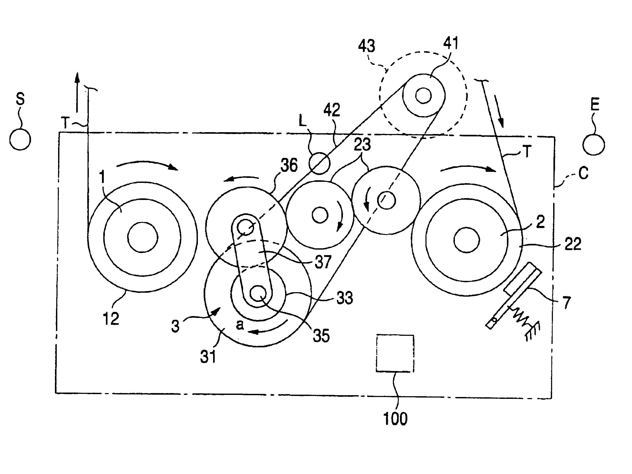
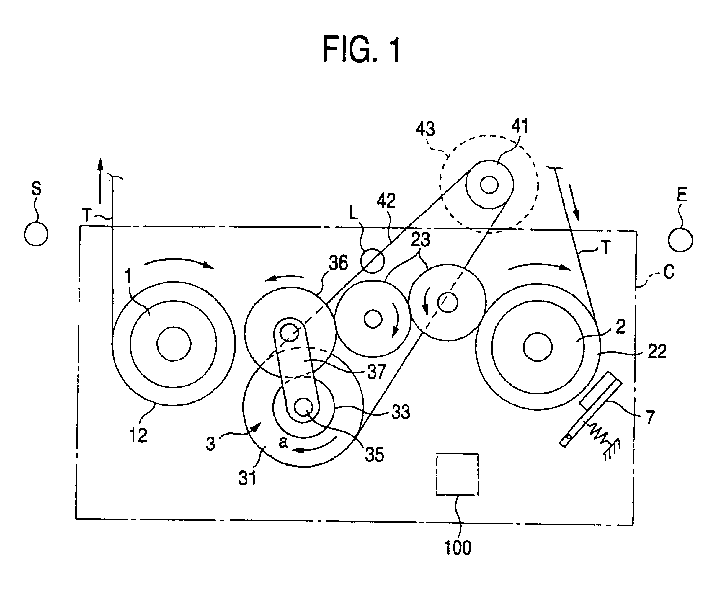
[0028]FIG. 1 is a schematic plan view of a braking device for a magnetic tape apparatus according to one embodiment of the present invention when a fast forward mode is executed. FIG. 2 is a schematic plan view for explaining a braking operation conducted by the braking device. FIG. 3 is a diagram for explaining a direct-coupled rotation mode of a switching unit 3. FIG. 4 is a diagram showing a slide rotation mode of the switching unit 3. FIG. 5 is a diagram presented as a time chart.

[0029]In FIG. 1, a braking device includes a supply reel table 1, a take-up reel table 2 and a switching unit 3. Gears 12 and 22 are respectively provided coaxially with the supply reel table 1 and the take-up reel table 2. A gear train 23 having a predetermined number of gears always engages with the gear 22 of the take-up reel table 2. A controller 100 such as CPU controls the operation of the breaking device.

[0030]The switching unit 3 includes a pulley 31, and a belt 42 fitted around the pulley 31 an...


PUM

PropertyMeasurementUnit
timeaaaaaaaaaa
timeaaaaaaaaaa
rotationaaaaaaaaaa

Abstract

A braking device for an magnetic tape apparatus includes a switching unit for selectively transmitting the rotation of a capstan motor to a take-up reel table or to a supply reel table, a clutch for changing the switching unit to a slide rotation mode or to a direct-coupled rotation mode, a brake, a loading motor for driving the brake, and an end sensor. Based on a tape end detection signal produced during an operation in a fast forward mode, the capstan motor is rotated in reverse to permit the switching unit to select a second path, while the switching unit is maintained in the direct-coupled mode. Thereafter, the capstan motor is halted, and the loading motor is rotated to use the brake to halt the take-up reel table.

Description

BACKGROUND OF THE INVENTION[0001]1. Field of the Invention[0002]The present invention relates to a braking device for a magnetic tape apparatus, particularly to a braking device for halting the feeding of magnetic tape from a supply reel when the amount of magnetic tape remaining on the supply reel is reduced in a fast forward mode.[0003]2. Description of the Related Art[0004]Well known braking devices for magnetic tape apparatuses are disclosed in JP-A-3-8160 (conventional example 1) and JP-A-5-114199 (conventional example 2).[0005]According to conventional example 1, various operating modes are selected depending on the position of a plate cam. In a fast forward mode, the plate cam renders a braking device inactive in accordance with an energization instruction provided for an electromagnet. When a tape end detector detects a terminal end of a tape, a detection signal is transmitted to a system controller. The system controller then simultaneously outputs an instruction to halt a ...

Claims


Application Information

Patent Timeline
Patent Type & Authority Patents(United States)
IPC IPC(8): G11B15/05G11B15/06G11B15/22G11B15/18G11B15/44
CPCG11B15/06G11B15/22G11B15/444
Inventor HAYASHI, RYUJIOKAZAKI, NOBUYUKI
Owner FUNAI ELECTRIC CO LTD
Why Eureka
Try Eureka