Adapter-connector and conductor set

a technology of adapter-connector and conductor, which is applied in the direction of connection contact member material, fixed connection, coupling device connection, etc., can solve the problems of failure of effective contact between the adapter-connector and the adapted electronic device, conductor may fail to be secured to the insulator, and at least three flaws of the conductor, so as to achieve convenient process, ensure effective contact, and ensure reliable securing

Inactive Publication Date: 2005-07-05
JU TED
View PDF3 Cites 14 Cited by
  • Summary
  • Abstract
  • Description
  • Claims
  • Application Information

AI Technical Summary

Benefits of technology

[0005]The primary purpose of the present invention is to provide a set of an adapter-connector and conductor that allows easier process, reliable securing and guaranteed effective contact with its adapted electronic device.
[0006]Another purpose of the present invention is to provide a set of an adapter-connector and conductor that offers higher reliability and lower contact resistance to ensure of good performance of the adapter-connector.
[0007]To achieve these purposes, the set of the adapter-connector and the conductor is comprised of a main portion, a resilient arm and a conduction part with the resilience arm and the conduction part extending in parallel from the main portion, and the resilient arm then bent in the opposite direction to extend for a certain length before being bent again for a certain angle, and a contact being provided at the terminal of the resilient arm at a point higher than the top of the main portion to allow easier process. reliable securing and guaranteed effective contact with the adapted electronic device.

Problems solved by technology

However, at least three flaws are observed with the conductor.
Firstly, with the adapter-connector being provided with a given height and the smaller length of the fixed part of the conductor, the conductor may fail to be secured to the insulator.
Secondly, the contact arm is shorter and yields smaller resilience, the contact arm is vulnerable to be deformed after several times of compression, leading to the failure of effective contact for the adapter-connector with the adapted electronic device, and the performance of the adapter-connector is compromised.
Thirdly, the process for the conductor is comparatively complicate, since it requires multiple folding.

Method used


Image

  • Adapter-connector and conductor set
  • Adapter-connector and conductor set
  • Adapter-connector and conductor set

Examples


Embodiment Construction

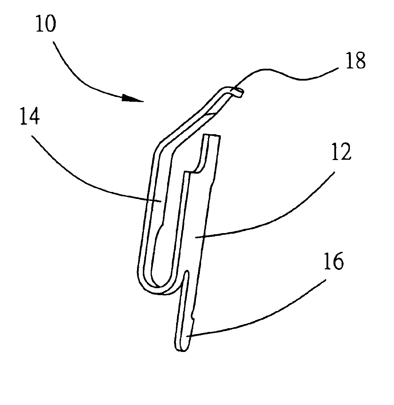
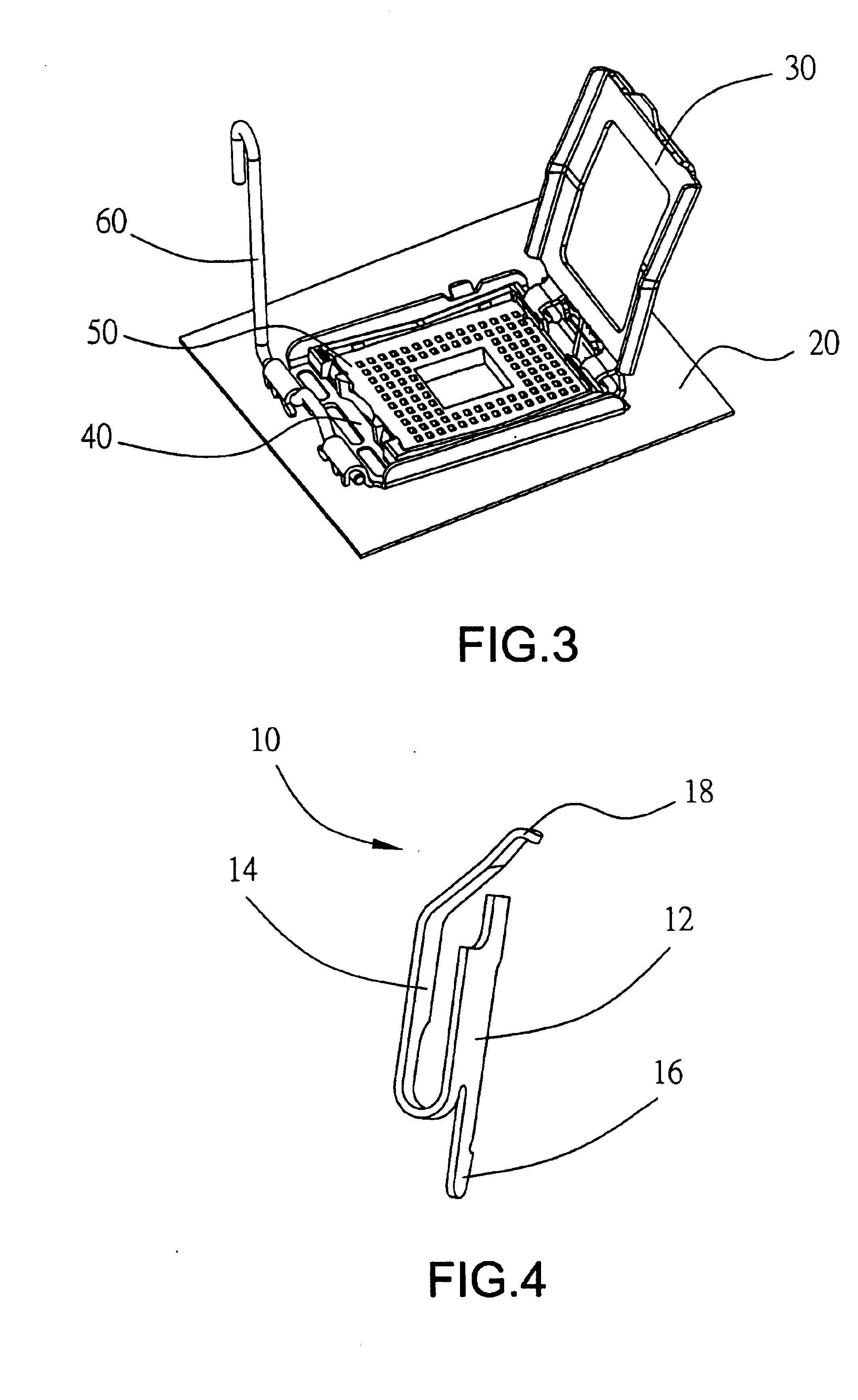
[0018]As illustrated in FIGS. 3, 4, and 5, a conductor 10 of the present invention is comprised of a main portion 12, a resilient arm 14 and a connection part 16 extend below the main portion 12 with the resilient arm 14 being further bent in opposition direction for 180 degrees backward to supercede the top of the main portion 12 and then folder towards the main portion 12 for a certain angle. A contact 18 is provided at the terminal of the resilient arm 14 at a level higher than the top of the main portion 12 to adapt to an electronic device (not illustrated). A mobile upper lid 30 and a mobile lower lid 40, a fixture 50 located between the upper and the lower lids 30, 40 and a dancer 60 used to buckle up the upper and the lower lids 30, 40 are connected to the adapter-connector of the present invention. Wherein, the fixture 50 contains multiple insulators 54 including multiple sinks 52, and multiple tin balls 56 (or any other devices that can be easily melted) are provided below ...


PUM


Abstract

A set of conductor and an adapter-connector to allow easier process, reliable securing and guaranteed effective contact with its adapted electronic device is characterized by that the conductor containing a main portion, a resilient arm and a conduction part; both of the resilient arm and the conduction part being extended in parallel from one end of the main portion; the resilient arm being further bent in opposite direction to extend for a certain length, then further bent for a certain angle; a contact being provided on the resilient arm at a level higher than that of the top of the main portion.

Description

BACKGROUND OF THE INVENTION[0001](a) Field of the Invention[0002]The present invention is related to a set of an adapter-connector and conductor, and more particularly, to a connector adapted with a compression contact conductor.[0003](b) Description of the Prior Art[0004]Connection between a connector and its adapted electronic device comes diversified. Within a compression contact type of connector is used to adapt to an electronic device, and the connection between the connector and the adapted electronic device is realized by means of a conductor. As illustrated in FIGS. 1 and 2 of the accompanying drawings, the conductor is comprised of a fixed part 1, a contact arm 2 extending upward from the fixed part 1, a connection arm 3 for material band bent and extending sideway from the contact arm 2, and a soldering end 4 extending downward from the fixed part 1 then bent backward for 90 degrees to connect a solder 41, e.g., a tin ball. Upon installation, the conductor is fixed to an ...

Claims


Application Information

Patent Timeline
Patent Type & Authority Patents(United States)
IPC IPC(8): H05K7/10H01R13/24H01R13/22
CPCH01R12/57H05K7/1069H01R13/24H01R12/716
Inventor JU, TED
Owner JU TED
Why Eureka
Try Eureka