Linear electrical machine for electric power generation or motive drive

a technology of electric power generation and motive drive, which is applied in the direction of dynamo-electric machines, synchronous machines with stationary armatures, electrical apparatus, etc., can solve the problems of noisy turbines, internal combustion engines and other power sources that are often too noisy for such applications

Inactive Publication Date: 2005-07-05
TIAX LLC
View PDF181 Cites 59 Cited by
  • Summary
  • Abstract
  • Description
  • Claims
  • Application Information

AI Technical Summary

Problems solved by technology

As a result, turbines, internal combustion engines and other power sources are often far too noisy for use in such applications.

Method used


Image

  • Linear electrical machine for electric power generation or motive drive
  • Linear electrical machine for electric power generation or motive drive
  • Linear electrical machine for electric power generation or motive drive

Examples


Embodiment Construction

[0024]Aspects of the invention are not limited to the details of construction and arrangement of components set forth in the following description or illustrative embodiments. That is, aspects of the invention are capable of being practiced or of being carried out in various ways. For example, various illustrative embodiments are described below in connection with an electric power generator. However, aspects of the invention may be used in a linear motor (e.g., a device that can output a linear mechanical motion in response to an electric signal provided to the device). Also, the phraseology and terminology used herein is for the purpose of description and should not be regarded as limiting. The use of “including,”“comprising,” or “having,”“containing”, “involving”, and variations thereof herein, is meant to encompass the items listed thereafter and equivalents thereof as well as additional items.

[0025]In one aspect of the invention, a linear electrical machine includes a movable p...


PUM


Abstract

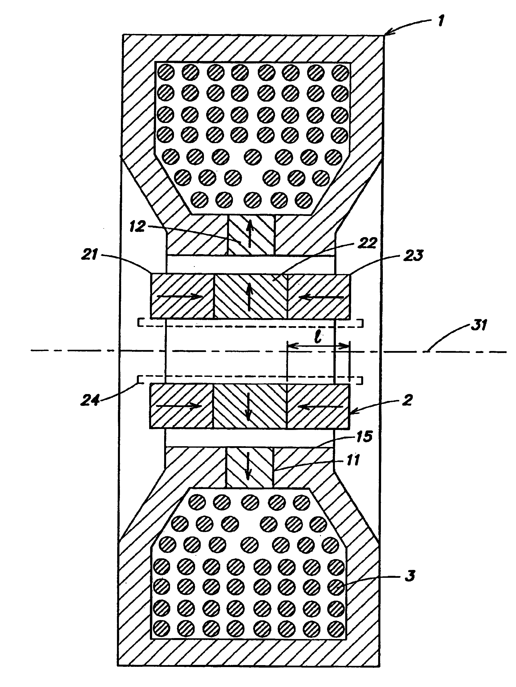
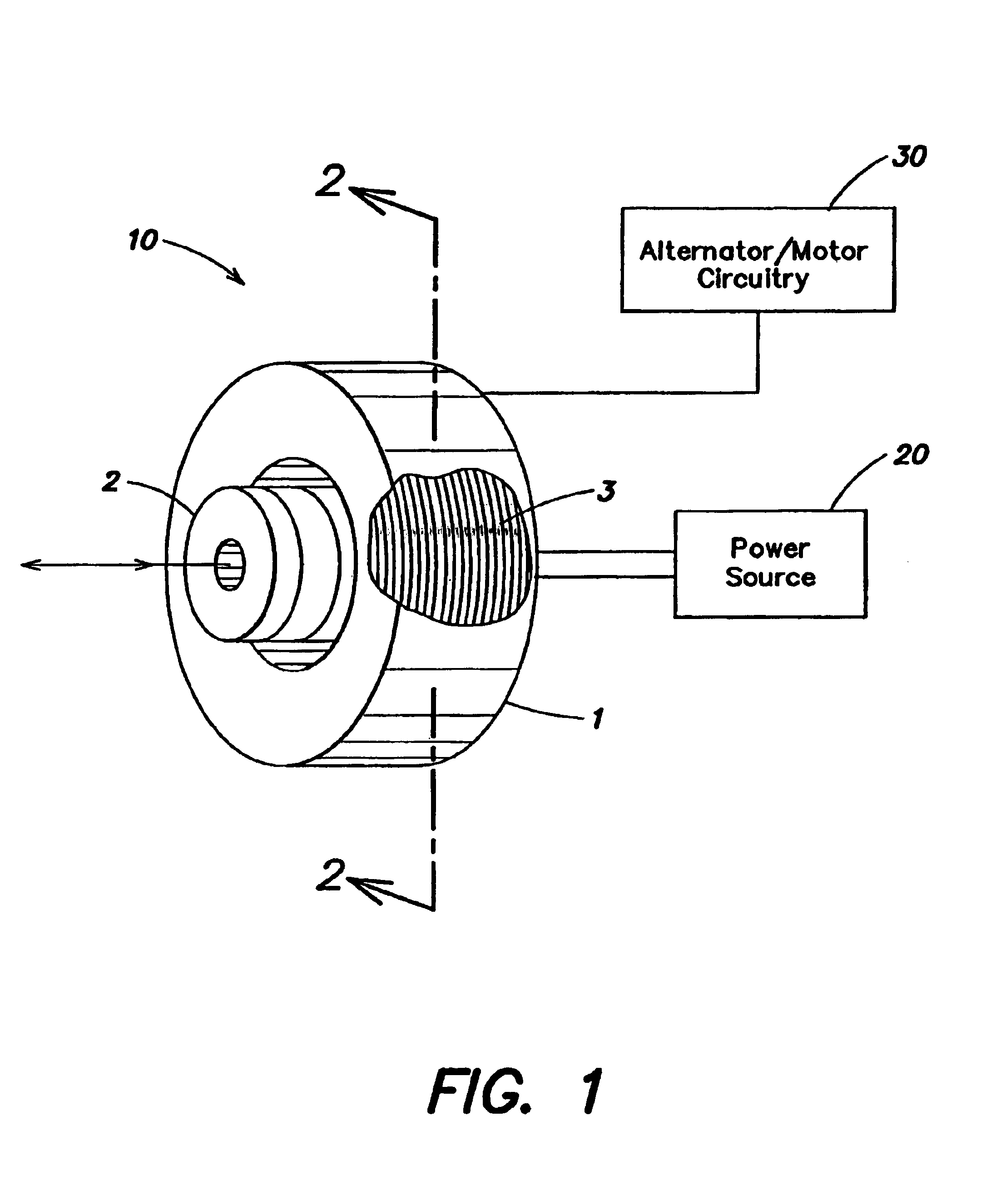
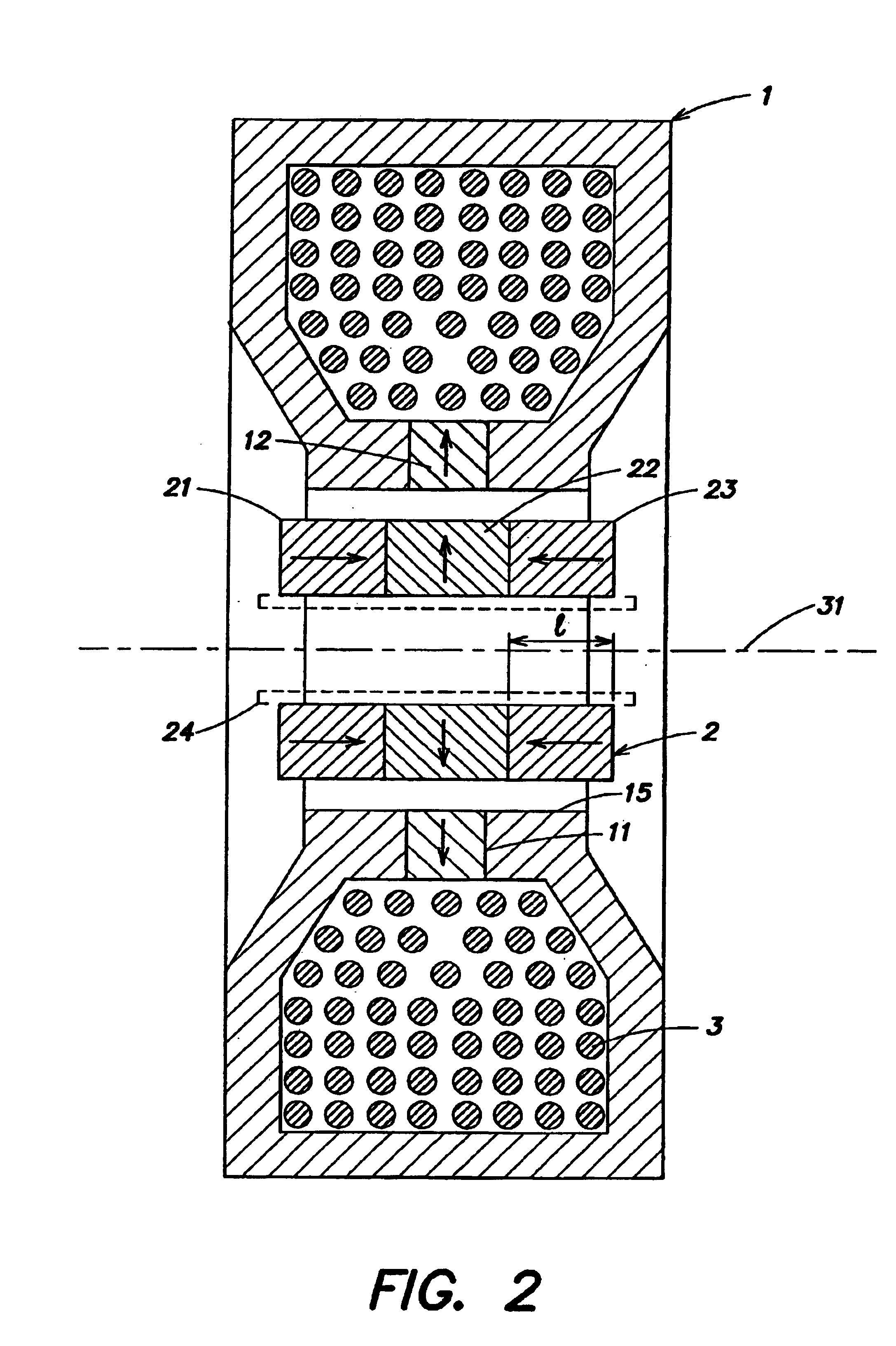
A linear electrical machine may function as an alternator or a motor. Three annular magnets may be provided that move relative to a core. The magnets may all have a different magnetic orientation. Two magnets may have a north pole oriented in a direction parallel to an axis along which the magnets move relative to the core. Another magnet may have a north pole oriented in a direction perpendicular to the axis.

Description

BACKGROUND OF INVENTION[0001]1. Field of Invention[0002]The invention relates to a linear electrical machine for electric power generation or motive drive.[0003]2. Discussion of Related Art[0004]Quiet and efficient electric power generation can be important in a variety of applications. For example, boats and other spaces having power generation systems in close proximity to people have a need for quiet operation. As a result, turbines, internal combustion engines and other power sources are often far too noisy for use in such applications. Free piston Stirling engines, however, operate fairly quietly and have been used to drive linear electrical machines also referred to as linear alternators to generate electric power. (The term “alternator” is used herein to generically refer to any type of electric power generation device, whether producing alternating current, direct current, or other forms of electric power. Except for the case of the automotive “alternator” which has a built ...

Claims


Application Information

Patent Timeline
Patent Type & Authority Patents(United States)
IPC IPC(8): H02K35/02H02K35/00H02K33/00H02K33/16
CPCH02K33/16H02K35/02
Inventor CHERTOK, ALLAN
Owner TIAX LLC
Why Eureka
Try Eureka