Digitizing apparatus

a technology of digital display and display device, which is applied in the direction of digital output to plotter, instruments, computing, etc., can solve the problems of difficult to see display b>11/b> and complex structure of display surface, and achieve the effect of simplifying the structure of display device and being easy to s

Inactive Publication Date: 2005-07-05
SANYO ELECTRIC CO LTD
View PDF12 Cites 19 Cited by
  • Summary
  • Abstract
  • Description
  • Claims
  • Application Information

AI Technical Summary

Benefits of technology

[0011]It is therefore an object of the present invention to simplify the structure of the display device and to design the display device to be easy to see.

Problems solved by technology

A problem arises in which the structure of the display surface 2 becomes complex.
Furthermore, since the resistance sheet 12 has a plurality of sheets, a problem arises in which the display 11 becomes hard to see due to the influence of light interference.

Method used


Image

  • Digitizing apparatus
  • Digitizing apparatus
  • Digitizing apparatus

Examples


Embodiment Construction

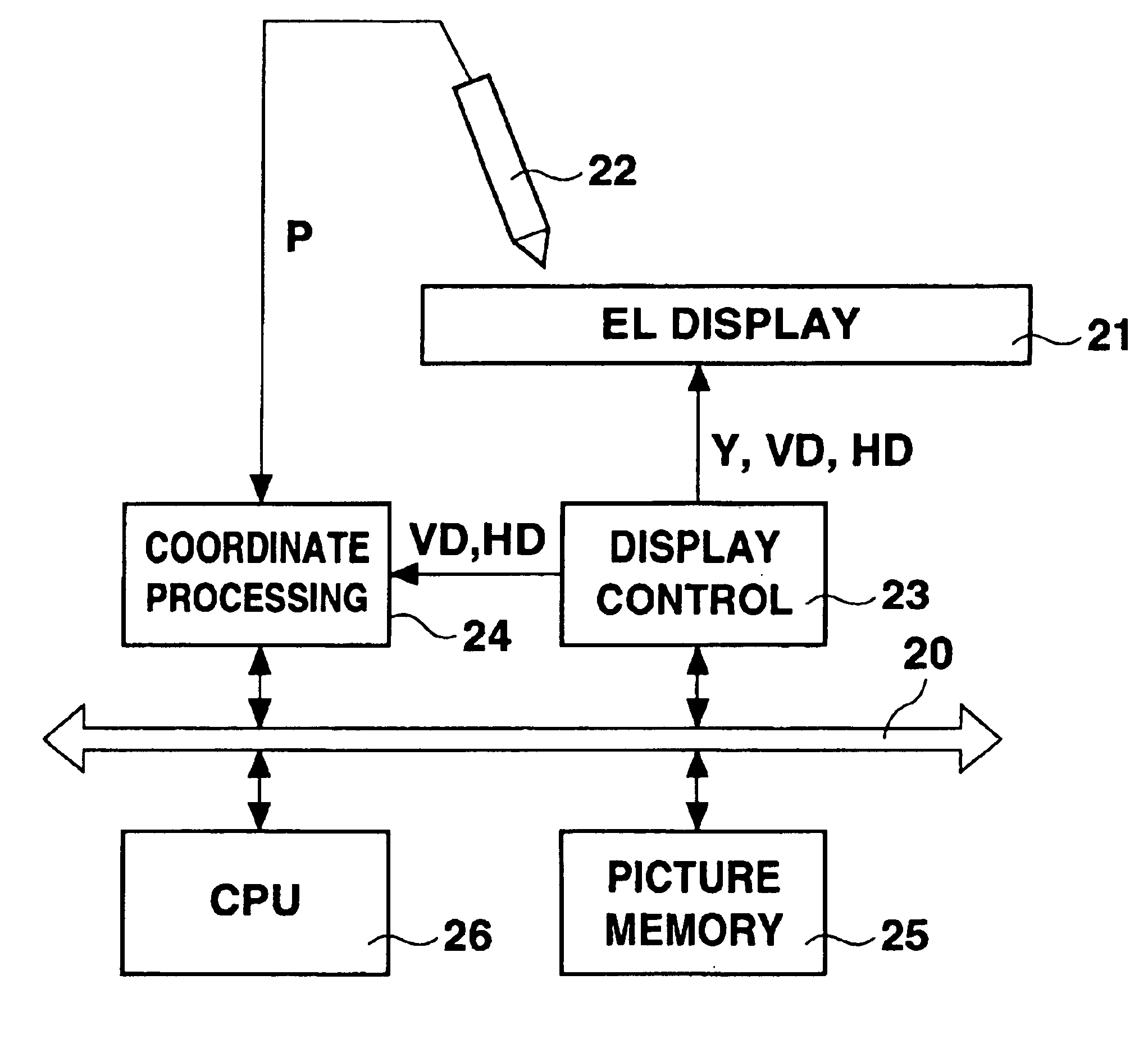
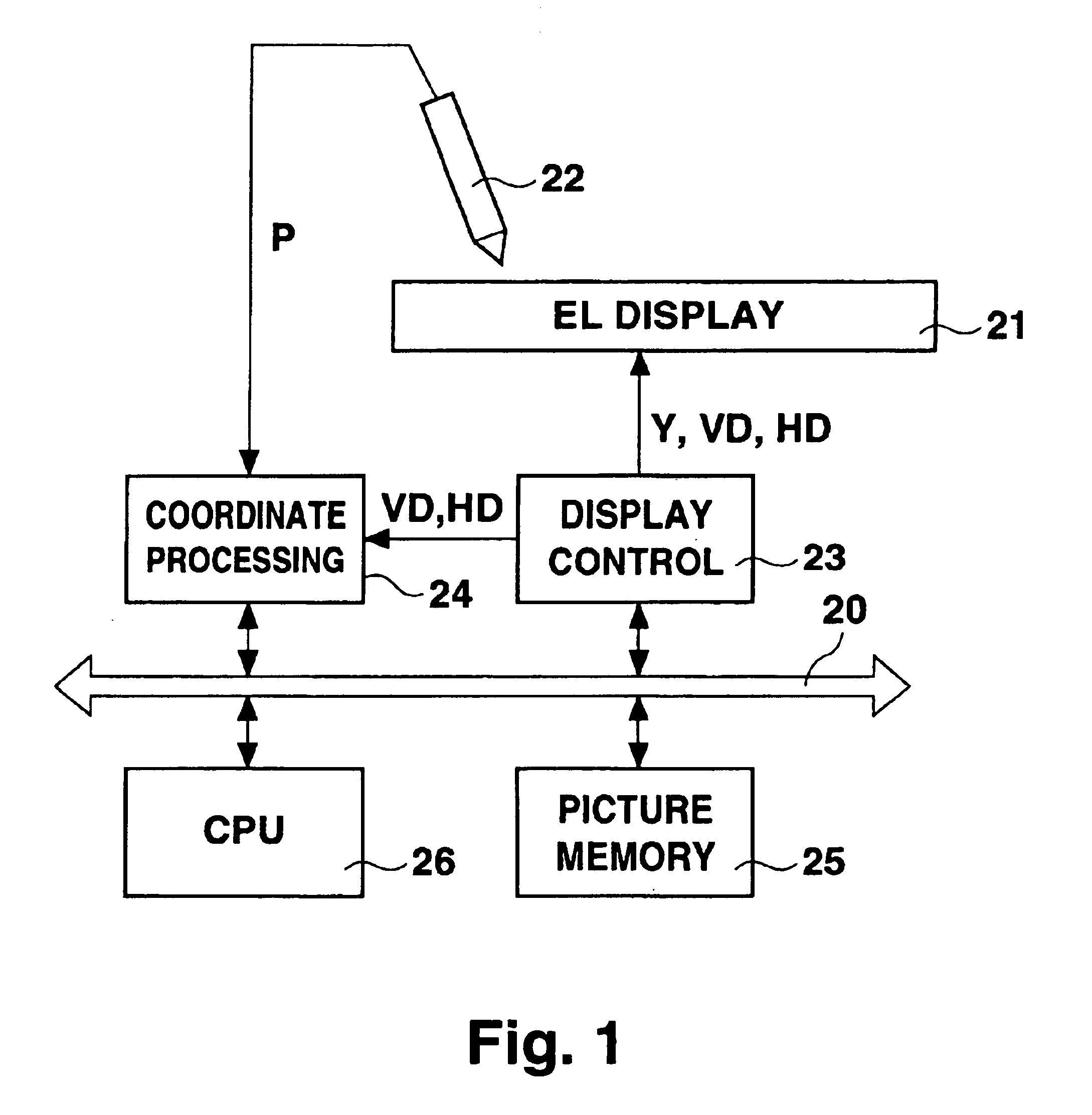
[0023]FIG. 1 is a block diagram showing an embodiment of the present invention. The digitizer as a digitizing apparatus of the present invention comprises an electroluminescence (EL) display 21, an input pen 22, a display control circuit 23, a coordinate processing circuit 24, a picture memory 25, and a CPU 26. This digitizer has the same form as the digitizer shown in FIG. 5 and has a display surface on which characters and graphics are drawn with the input pen 22. The surface of the EL display 21 uses a transparent substrate (such as a glass substrate) on which is formed emissive elements (EL elements).

[0024]The EL display 21 has a plurality of display pixels (EL elements) arranged in a matrix, and forms the display surface of the digitizer. The EL display 21 displays a predetermined picture by causing the plurality of display pixels to emit light in accordance with the picture signal Y that is supplied from the display control circuit 23. The input pen 22 has an optical sensor fo...


PUM


Abstract

Graphics are drawn with an input pen, which is provided with an optical sensor at its tip, on a display surface of an EL display. At this time, the EL display is caused to emit light in dot sequence, and the position of the input pen is detected as coordiante information on the basis of timing of light emission of the EL display and timing of light emission detection of the input pen.

Description

BACKGROUND OF THE INVENTION[0001]1. Field of the Invention[0002]The present invention relates to a digitizing apparatus or digitizer to be used as an input device for computer equipment.[0003]2. Description of the Related Art[0004]FIG. 5 is a perspective diagram showing the structure of a digitizer as a digitizing apparatus and FIG. 6 is a block diagram showing its configuration.[0005]A digitizer 1 has a display surface 2 and is connected to computer equipment via a cable 3. On the display surface 2 is displayed a picture 4 in accordance with picture information that is supplied from the computer equipment. By writing a characters or drawing a graphic on the display surface 2 using an input pen 5, the tracing is sent to the computer equipment at predetermined time intervals as coordinate information.[0006]The digitizer 1 comprises a flat display 11, a resistance sheet 12, a display control circuit 13, a coordinate processing circuit 14, a picture memory 15, and a CPU 16. The flat di...

Claims


Application Information

Patent Timeline
Patent Type & Authority Patents(United States)
IPC IPC(8): G06F3/033G06F3/13G09G5/00G06F3/042G06F3/03G06F3/041G09G3/32
CPCG06F3/03542G06F3/0386G09G3/32G09G2300/0842G09G2310/0251G06F3/03
Inventor KOBAYASHI, MITSUGUUEHARA, HISAO
Owner SANYO ELECTRIC CO LTD
Why Eureka
Try Eureka