Support stand

a support structure and stand technology, applied in the direction of mountings, microlithography exposure equipment, instruments, etc., can solve the problems of poor support structure results, reduced production yields, and difficulty in installation,

Active Publication Date: 2005-07-05
POWERCHIP SEMICON MFG CORP
View PDF1 Cites 2 Cited by
  • Summary
  • Abstract
  • Description
  • Claims
  • Application Information

AI Technical Summary

Benefits of technology

[0010]Because the support stand of the claimed invention is an H-beam, which has some advantages such as good rigidity, small size, material standard easily obtained, easy to install, and good performance for fixing, it can prevent an optic axis shift caused by poor support performance due to outside vibration, and then make sure that the exposure light source goes through the operating machine steadily. Furthermore, the claimed invention uses a signal emitter and a signal receiver for detecting. If an optic axis shifts, a warning signal will be emitted to warn operators to adjust or stop the semiconductor process, to prevent the manufacture of poor quality products. In addition, the H-beam of the present invention is easy to assemble and disassemble, so it can reduce the occurrence of overlapping pipes and the cost of time to move pipelines.

Problems solved by technology

Furthermore, operating machines must be placed in the clean room to prevent particles from polluting products and reducing production yields.
However, it is very expensive to construct a clean room.
Therefore, in the prior art there are some drawbacks such as poor results for support structures and difficulty of installation.
This will cause exposure light source going through the operating machine to have a phenomenon of axes shifts and poor intensity and uniformity of the exposure light source, and thereby influence the critical dimension and the throughput of semiconductor product.

Method used


Image

  • Support stand
  • Support stand
  • Support stand

Examples


Embodiment Construction

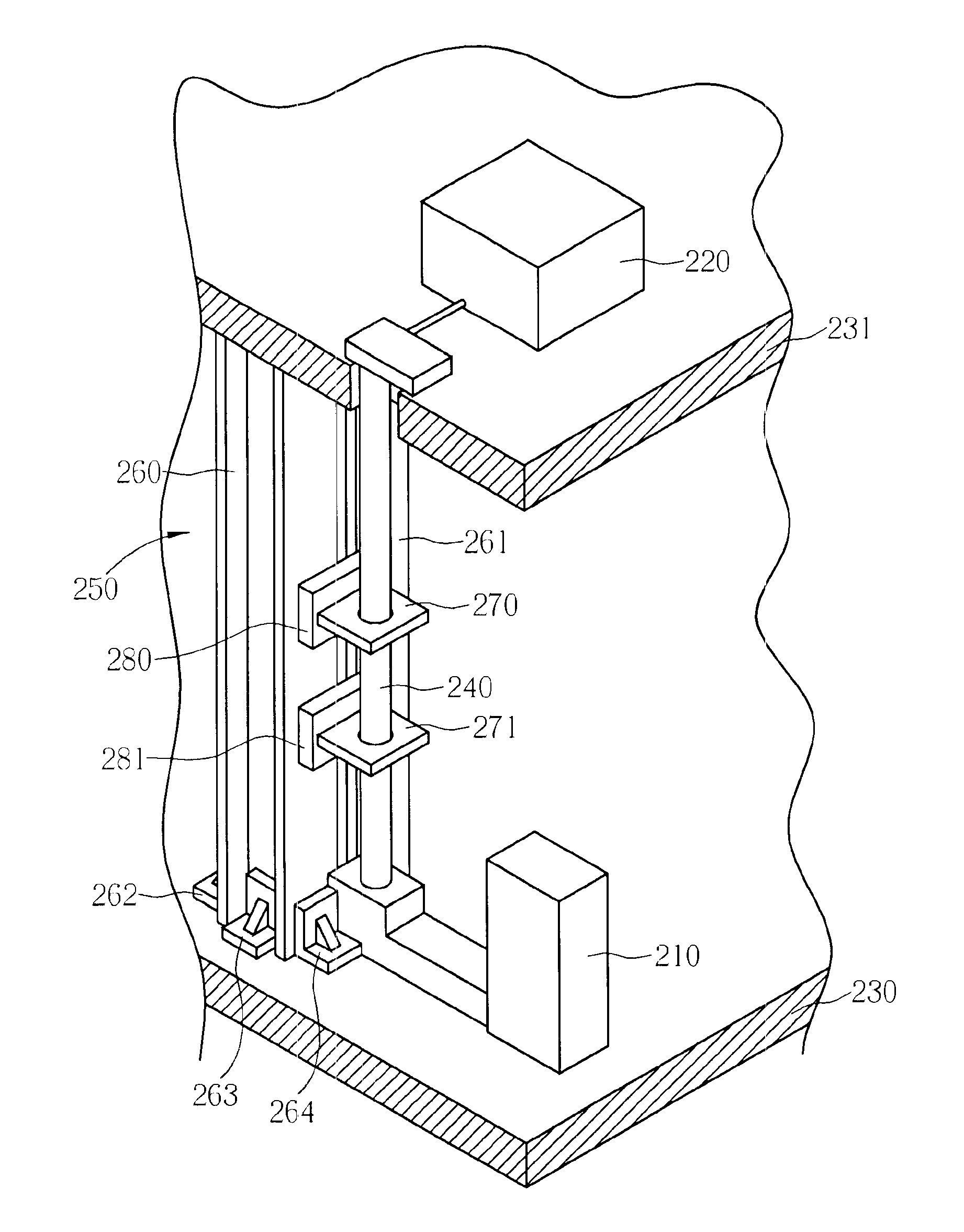
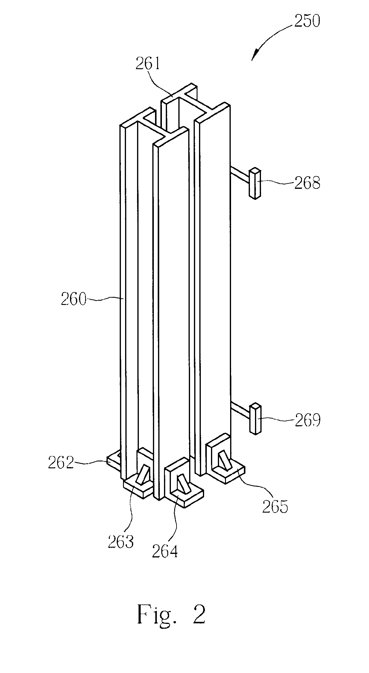
[0017]Please refer to FIG. 2 and FIG. 3. FIG. 2 is a three dimensional diagram of a support stand 250 of the present invention. FIG. 3 is a side view of the support stand 250, which is shown in FIG. 2. As shown in FIG. 2 and FIG. 3, the support stand 250 includes H-beams 260,261 that are parallel to each other and support elements 262-267 for jointing the H-beams 260,261 with the floor and supporting the H-beams 260,261. For example, as shown in FIG. 4, one end of the support elements 262-264 is set on the first part such as the bottom of the H-beam 260 and the other end is set on the ground of a floor 230. According to this design, the H-beam 260 and the floor 230 can be jointed well and the H-beam 260 can be supported sufficiently. Since the quantity and model of the support elements 262-267 referred to before may depend on the practical demand, the module may be different sizes and quantity such as six angle support bases. The shape of the angle support base may be the shape of “...


PUM

PropertyMeasurementUnit
angleaaaaaaaaaa
energyaaaaaaaaaa
exposure energyaaaaaaaaaa

Abstract

The present invention provides a support stand. The support stand includes at least one H-beam set between a light source of an exposure machine and an operating machine of that to support an optical axis of the exposure machine, at least one supporting element set on a first part of the H-beam, a signal emitter set on a second part of the H-beam, and a signal receiver, receiving a signal sent from the signal emitter, set on a third part of the H-beam. The signal emitter and the signal receiver are used for detecting an optical axis shift.

Description

BACKGROUND OF INVENTION[0001]1. Field of the Invention[0002]The present invention provides a support stand, which can support an optical axis of an exposure machine.[0003]2. Description of the Prior Art[0004]Presently, subsidiary machines of high-energy exposure machines such as light source generators are mostly placed separately with operating machines such as steppers and scanners in semiconductor foundries to prevent operators or machines from being hurt or influenced by heat, particles, noise, vibration and high-energy radiation generated by the light source generators. Furthermore, operating machines must be placed in the clean room to prevent particles from polluting products and reducing production yields. However, it is very expensive to construct a clean room. To keep space for more operating machines, light source generators of exposure machines and operating machines are mostly placed on different floors and then the cost of foundries is reduced. In addition, there are n...

Claims


Application Information

Patent Timeline
Patent Type & Authority Patents(United States)
IPC IPC(8): G02B27/62G03F7/20
CPCG02B27/62G03F7/70991G03F7/70833
Inventor WANG, HUNG-CHICHEN, MOU-SIRNKUO, CHUNG-MING
Owner POWERCHIP SEMICON MFG CORP
Why Eureka
Try Eureka