Method and apparatus providing a multi-function terminal for a power supply controller
What is Al technical title?
Al technical title is built by PatSnap Al team. It summarizes the technical point description of the patent document.
a multi-functional terminal and power supply controller technology, applied in the direction of electric variable regulation, process and machine control, instruments, etc., can solve the problems of increasing costs and additional external components, and substantial increase in power consumption by providing additional functionality
Inactive Publication Date: 2005-07-05
POWER INTEGRATIONS INC
View PDF5 Cites 62 Cited by
Summary
Abstract
Description
Claims
Application Information
AI Technical Summary
This helps you quickly interpret patents by identifying the three key elements:
Problems solved by technology
Method used
Benefits of technology
Problems solved by technology
Consequently, each additional function generally translates into an additional pin on the power supply controller chip, which translates into increased costs and additional external components.
Another consequence of providing additional functionality to power supply controllers is that there is sometimes a substantial increase in power consumption by providing the additional functionality.
Method used
Image
Click on the blue label to locate the original text in one second.
Reading with bidirectional positioning of images and text.
Examples
Embodiment Construction
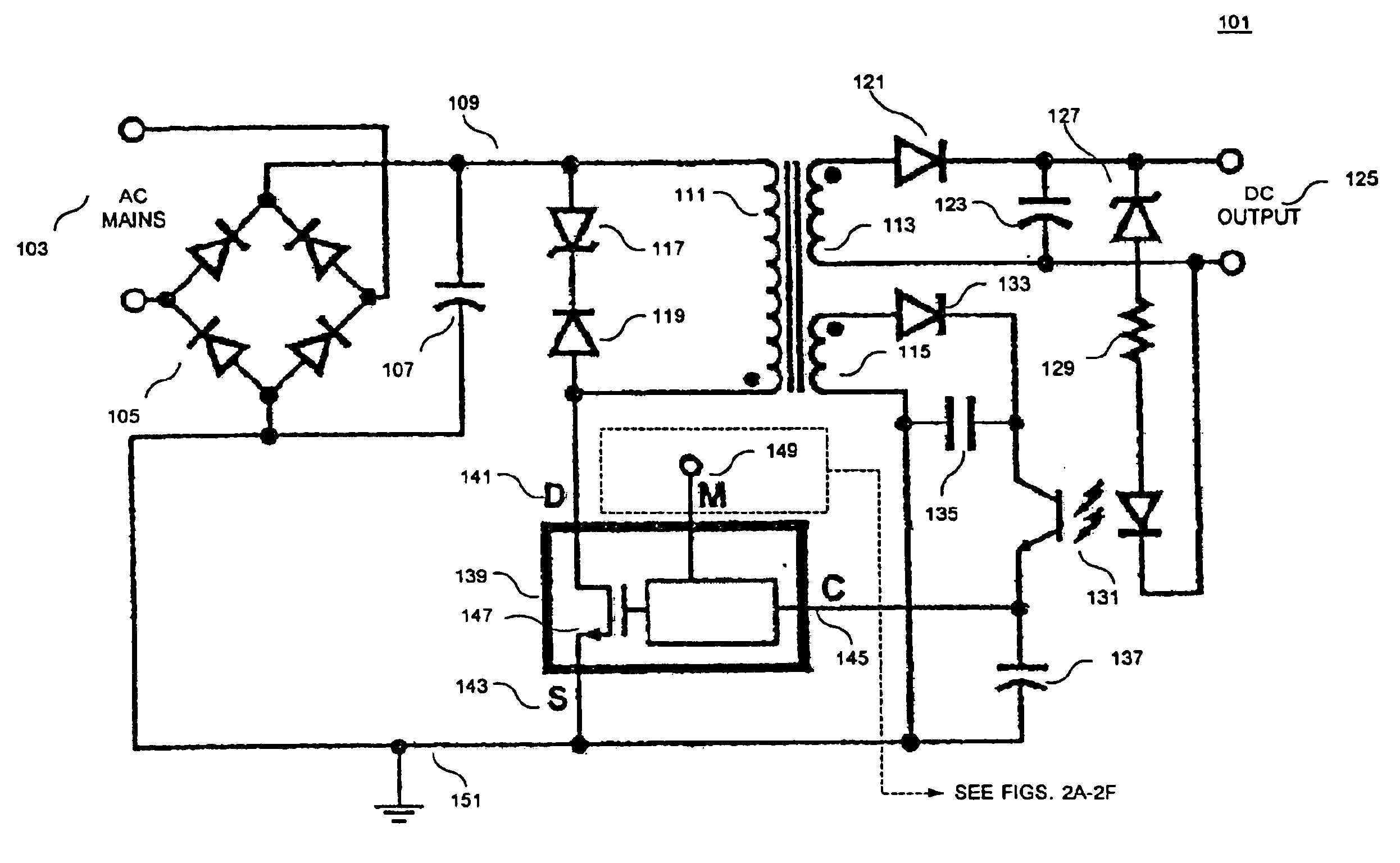
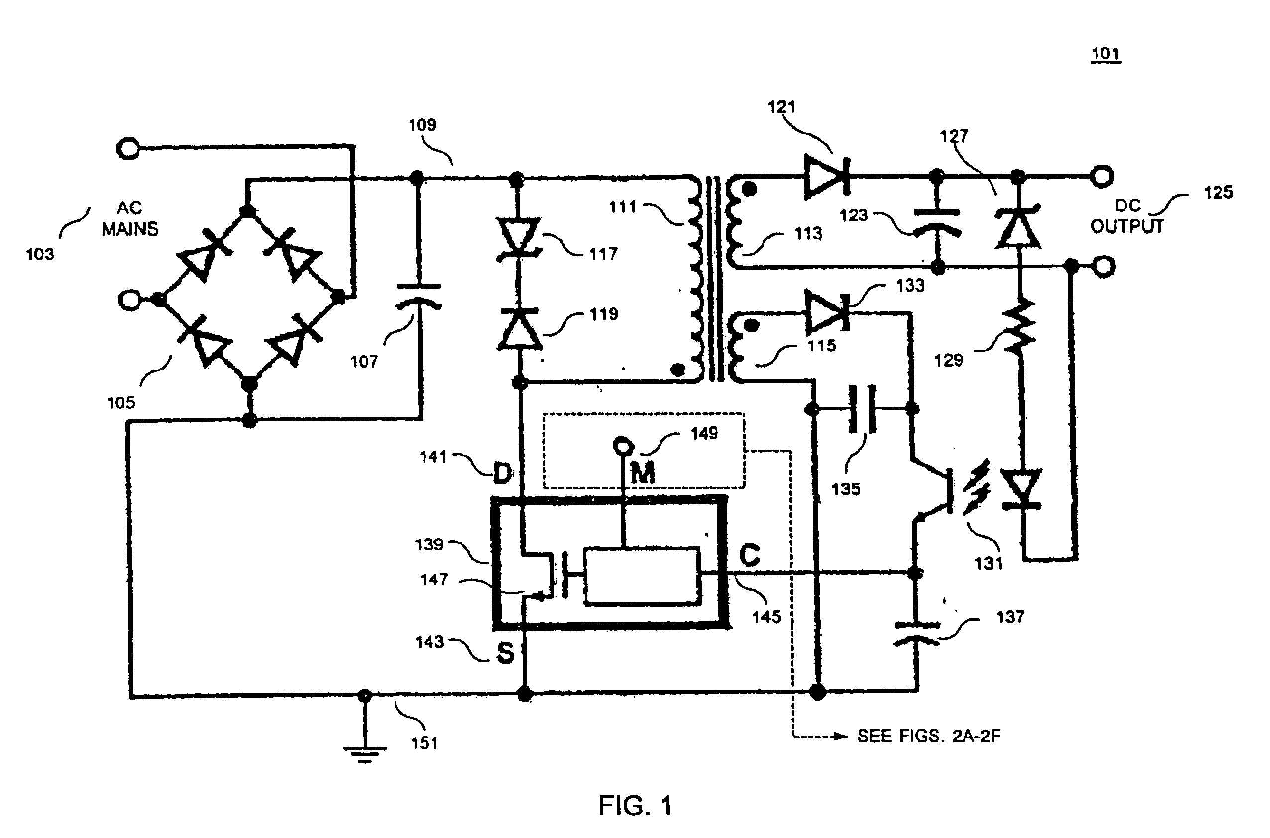
[0025]A method and an apparatus providing a multi-function terminal in a power supply controller is disclosed. In the following description, numerous specifically details are set forth in order to provide a thorough understanding of the present invention. It will be apparent, however, to one having ordinary skill in the art that the specific detail need not be employed to practice the present invention. In other instances, well-known materials or methods have not been described in detail in order to avoid obscuring the present invention.
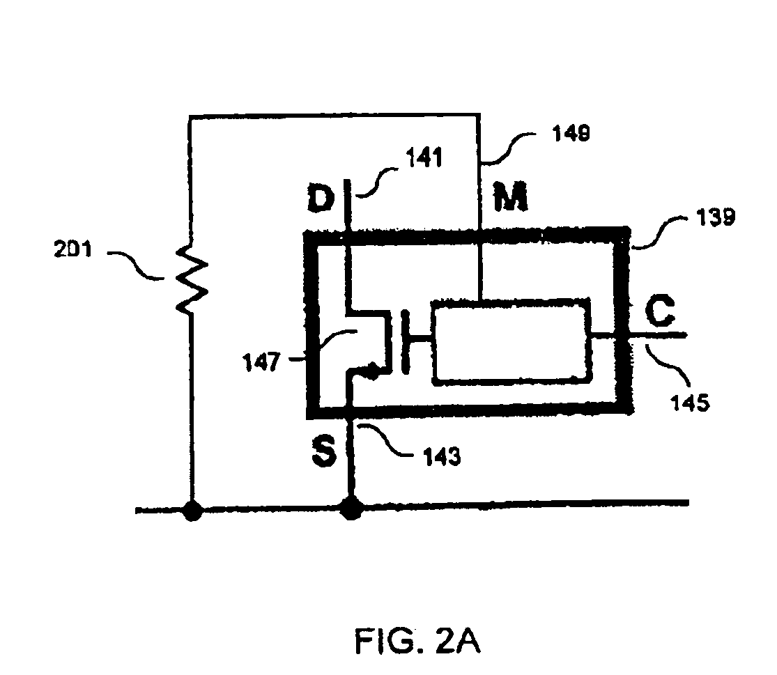
[0026]In one embodiment of the present invention, a power supply controller is provided with the functionality of being able to remotely turn on and off the power supply. In another embodiment, the power supply controller is provided with the functionality of being able to externally set the current limit of a power switch in the power supply controller, which makes it easier to prevent saturation of the transformer reducing transformer size and cost...
PUM
Abstract
A power supply controller having a multi-function terminal. In one embodiment, a power supply controller for switched mode power supply includes a drain terminal, a source terminal, a control terminal and a multi-function terminal. The multi-function terminal may be configured in a plurality of ways providing any one or some of a plurality of functions including on/off control, external current limit adjustments, under-voltage detection, over-voltage detection and maximum duty cycle adjustment. The operation of the multi-function terminal varies depending on whether a positive or negative current flows through the multi-function terminal. A short-circuit to ground from the multi-function terminal enables the power supply controller. A short-circuit to a supply voltage from the multi-function terminal disables the power supply controller. The current limit of an internal power switch of the power supply controller may be adjusted by externally setting a negative current from the multi-function terminal. The multi-function terminal may also be coupled to the input DC line voltage of the power supply through a resistance to detect an under-voltage condition, an over-voltage condition and/or adjust the maximum duty cycle of power supply controller. Synchronization of the oscillator of the power supply controller may also be realized by switching the multi-function terminal to power or ground at the desired times.
Description
[0001]This is a Continuation of U.S. application Ser. No. 10 / 349,621, filed Jan. 22, 2003, now U.S. Pat. No. 6,643,153, which is a continuation of U.S. application Ser. No. 10 / 167,557, filed Jun. 11, 2002, now U.S. Pat. No. 6,538,908 B2, which is a continuation of Ser. No. 09 / 405,209, filed Sep. 24, 1999, now U.S. Pat. No. 6,462,971 B1.BACKGROUND OF THE INVENTION[0002]1. Field of the Invention[0003]The present invention relates generally to power supplies and, more specifically, the present invention relates to a switched mode power supply controller.[0004]2. Background Information[0005]Electronic devices use power to operate. Switched mode power supplies are commonly used due to their high efficiency and good output regulation to power many of today's electronic devices. In a known switched mode power supply, a low frequency (e.g. 50 Hz or 60 Hz mains frequency), high voltage alternating current (AC) is converted to high voltage direct current (DC) with a diode rectifier and capaci...
Claims
Application Information
Patent Timeline
Application Date:The date an application was filed.
Publication Date:The date a patent or application was officially published.
First Publication Date:The earliest publication date of a patent with the same application number.
Issue Date:Publication date of the patent grant document.
PCT Entry Date:The Entry date of PCT National Phase.
Estimated Expiry Date:The statutory expiry date of a patent right according to the Patent Law, and it is the longest term of protection that the patent right can achieve without the termination of the patent right due to other reasons(Term extension factor has been taken into account ).
Invalid Date:Actual expiry date is based on effective date or publication date of legal transaction data of invalid patent.
Patent Type & Authority Patents(United States)
IPC IPC(8): H02M1/00H02M3/335H02M3/24H02M1/32
CPCH02M1/32H02M3/33507
Inventor BALAKRISHNAN, BALUDJENGUERIAN, ALEX B.LUND, LEIF O.