
Method and apparatus for manufacturing coaxial cable with composite inner conductor

a composite inner conductor and coaxial cable technology, applied in the field of coaxial cables, can solve the problems of time-consuming, complex multi-step manufacturing, and add considerably to the cost of manufacturing a coaxial cable with a composite core, and achieve the effect of efficient coaxial cable manufacturing

Inactive Publication Date: 2005-07-12
COMMSCOPE INC
View PDF17 Cites 38 Cited by
  • Summary
  • Abstract
  • Description
  • Claims
  • Application Information

AI Technical Summary

Benefits of technology

[0007]In view of the foregoing background, it is therefore an object of the present invention to provide a method and apparatus for efficiently making a coaxial cable that has a composite core.
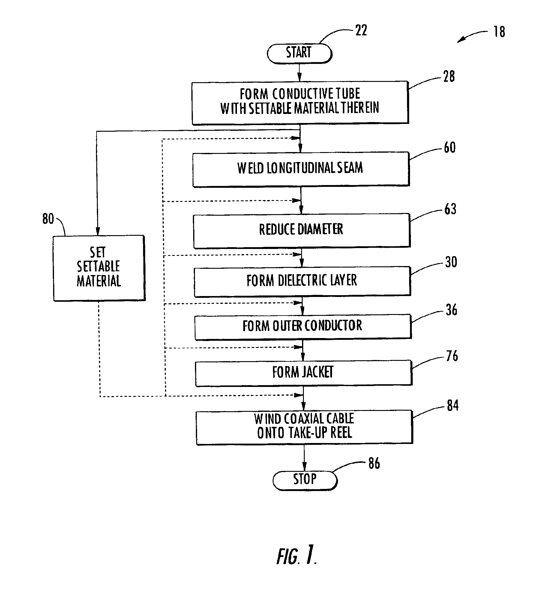
[0008]This and other objects, features, and advantages in accordance with the present invention are provided by a method for making a coaxial cable that includes forming a conductive tube and setting a settable material within the conductive tube to thereby define an inner conductor. The method further includes forming a dielectric layer around the inner conductor, and forming an outer conductor around the dielectric layer. The settable material may be water-blocking as well as supportive, and the method permits, for example, the manufacture of such a coaxial cable in a single pass so that it is made more efficiently and at a reduced cost relative to other modes of manufacturing such cables.

Problems solved by technology

Such multi-step manufacturing can be complex and time consuming.
Accordingly, it can also add considerably to the costs of manufacturing a coaxial cable with a composite core.

Method used


Image

  • Method and apparatus for manufacturing coaxial cable with composite inner conductor
  • Method and apparatus for manufacturing coaxial cable with composite inner conductor
  • Method and apparatus for manufacturing coaxial cable with composite inner conductor

Examples


Embodiment Construction

[0031]The present invention will now be described more fully hereinafter with reference to the accompanying drawings, in which preferred embodiments of the invention are shown. This invention may, however, be embodied in many different forms and should not be construed as limited to the embodiments set forth herein. Rather, these embodiments are provided so that this disclosure will be thorough and complete, and will fully convey the scope of the invention to those skilled in the art. Like numbers refer to like elements throughout, and prime and multiple prime notation indicate similar elements in alternate embodiments.

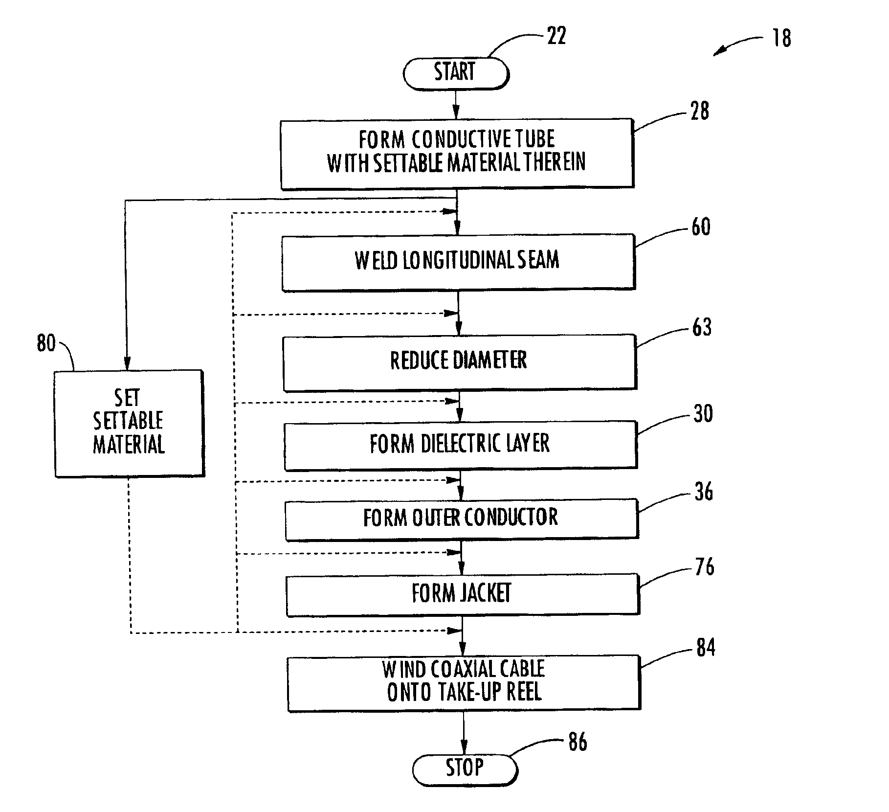
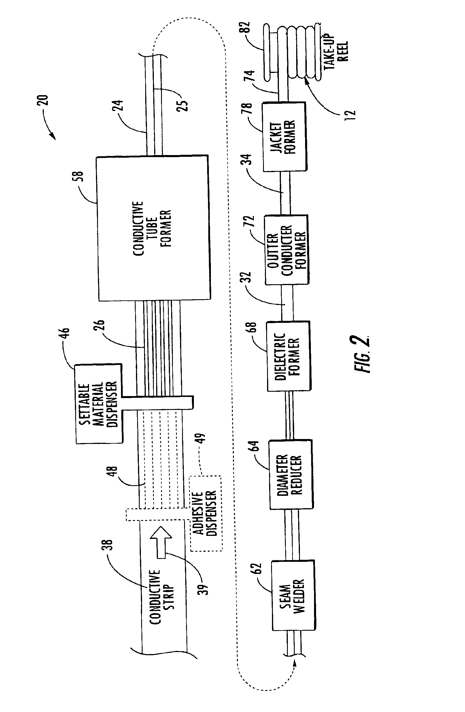
[0032]Referring initially to FIGS. 1-3, a method and apparatus 20 of making coaxial cable 12 according to the present invention are described. As illustrated by the steps of flow diagram 18, after the start (Block 22), the method illustratively continues with the formation of a conductive tube 24 (Block 28) with settable material 26 therein. The setting of a settable ...


PUM

PropertyMeasurementUnit
Temperatureaaaaaaaaaa
Dielectric polarization enthalpyaaaaaaaaaa
Pressureaaaaaaaaaa

Abstract

A method of making a coaxial cable includes forming a conductive tube and setting a settable material therein to define an inner conductor. Forming may include advancing a conductive strip and bending it into a tube having a longitudinal seam. The settable material may be dispensed onto the conductive strip continuously with the forming. Alternately, the settable material may be dispensed onto the conductive strip prior to advancing. The dispensing may use a puller cord as the settable material or carrying some or all of the settable material. The method may further include forming a dielectric layer surrounding the inner conductor, and forming an outer conductor surrounding the dielectric layer.

Description

FIELD OF THE INVENTION[0001]The present invention relates to the field of cables, and, more particularly, to coaxial cables.BACKGROUND OF THE INVENTION[0002]Coaxial cables are widely used to carry high frequency electrical signals. Coaxial cables have a relatively high bandwidth and low signal losses, are mechanically robust, and are relatively low cost. A coaxial cable typically includes an elongate inner conductor, a tubular outer conductor, and a dielectric separating the inner and outer conductors. The dielectric may be, for example, a plastic foam material. An outer insulating jacket may be applied to surround the outer conductor.[0003]One particularly advantageous use of coaxial cable is for connecting electronics at a cellular or wireless base station to an antenna mounted at the top of a nearby antenna tower. For example, the transmitter and receiver located in an equipment shelter may be coupled via coaxial cables to antennas carried by the antenna tower. A typical installa...

Claims


Application Information

Patent Timeline
IPC IPC(8): H01B13/016H01B11/18H01B13/00
CPCH01B11/1804H01B13/0162Y10T29/49117Y10T29/49123H01B13/22H01B13/067H01B11/1834H01B11/1869H01B11/1808
Inventor ADAMS, SCOTT M.
Owner COMMSCOPE INC
Learn More