Flywheel for an internal combustion engine

a technology of internal combustion engine and flywheel, which is applied in the direction of electric ignition installation, mechanical equipment, machines/engines, etc., can solve the problems of low loss caused by turbulence, and achieve the effects of low overall weight, adequate supply, and high moment of inertia

Inactive Publication Date: 2005-07-12
ANDREAS STIHL AG & CO KG
View PDF2 Cites 1 Cited by
  • Summary
  • Abstract
  • Description
  • Claims
  • Application Information

AI Technical Summary

Benefits of technology

[0004]It is an object of the invention to provide a flywheel which has a high moment of inertia while having a low overall weight and simultaneously ensuring an adequate supply of cooling air.
[0006]The center of gravity of the permanent magnet can be displaced far outwardly, that is, at a large distance from the rotational axis, by arranging the long edges of the permanent magnet parallel to the rotational axis of the flywheel. The moment of inertia of the flywheel then increases for the same weight of the flywheel. An arrangement of the magnet in this way leads to the situation that the vane configuration has only a very slight elevation in the region of the magnet. The influence on the movement of air can, however, be held low by a flow-facilitating configuration of the flywheel.
[0007]Advantageously, the permanent magnet extends at least over half of the elevation of the flywheel measured in the direction of the rotational axis. It is practical that pole shoes are mounted on both sides of the permanent magnet in the peripheral direction of the flywheel. The pole shoes guide the magnetic field on both sides of the permanent magnet to the outer periphery of the flywheel. A flow-favorable configuration of the flywheel is achieved in that the elevation of the pole shoes, which is measured in the direction of the longitudinal axis, is greater on the side facing toward the permanent magnet than the elevation on the side facing away from the permanent magnet. The ends of the pole shoes, which lie in the peripheral direction, run especially toward each other in an arcuate shape. In this way, the influence of the magnet on the moved air quantity can be held low, the magnet being mounted in the region of the vane configuration. The arcuately-shaped configuration prevents sharp edges in the course of flow. The uniform flow, which is provided hereby, leads to the situation that the losses caused by turbulence are low.

Problems solved by technology

The uniform flow, which is provided hereby, leads to the situation that the losses caused by turbulence are low.

Method used


Image

  • Flywheel for an internal combustion engine
  • Flywheel for an internal combustion engine

Examples


Embodiment Construction

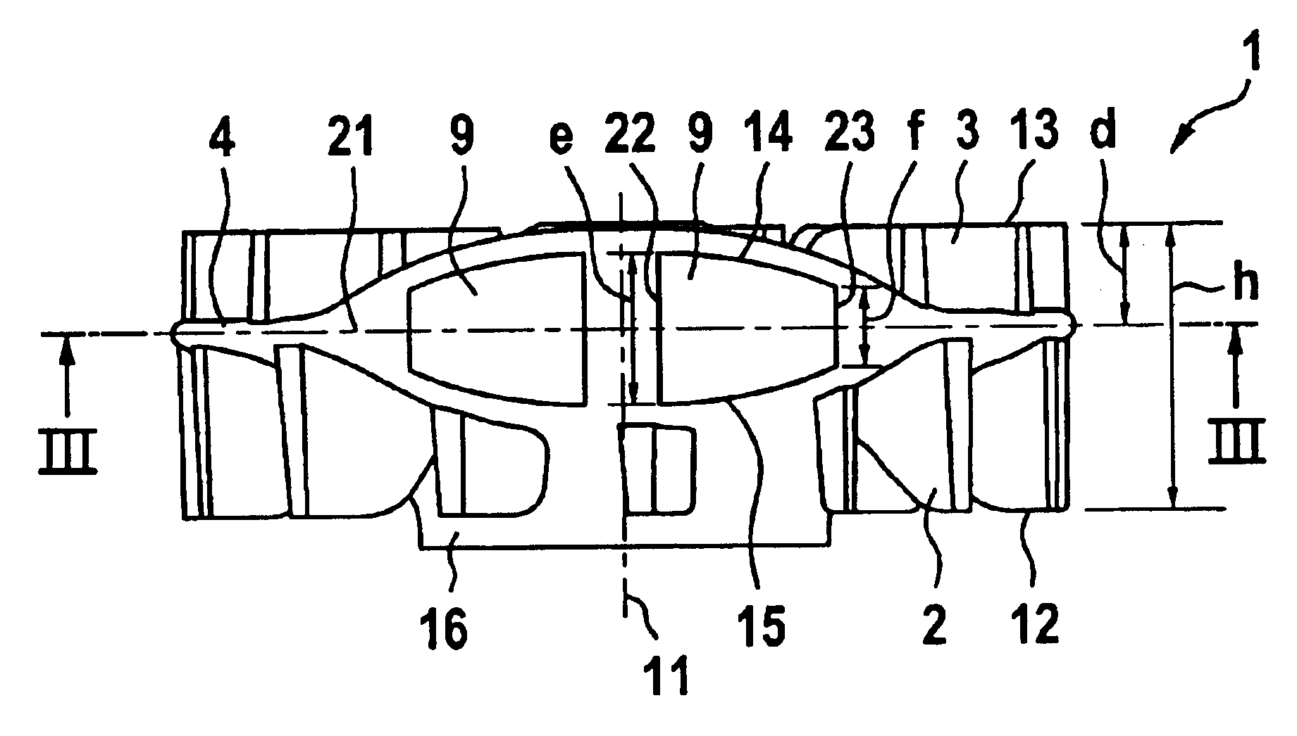
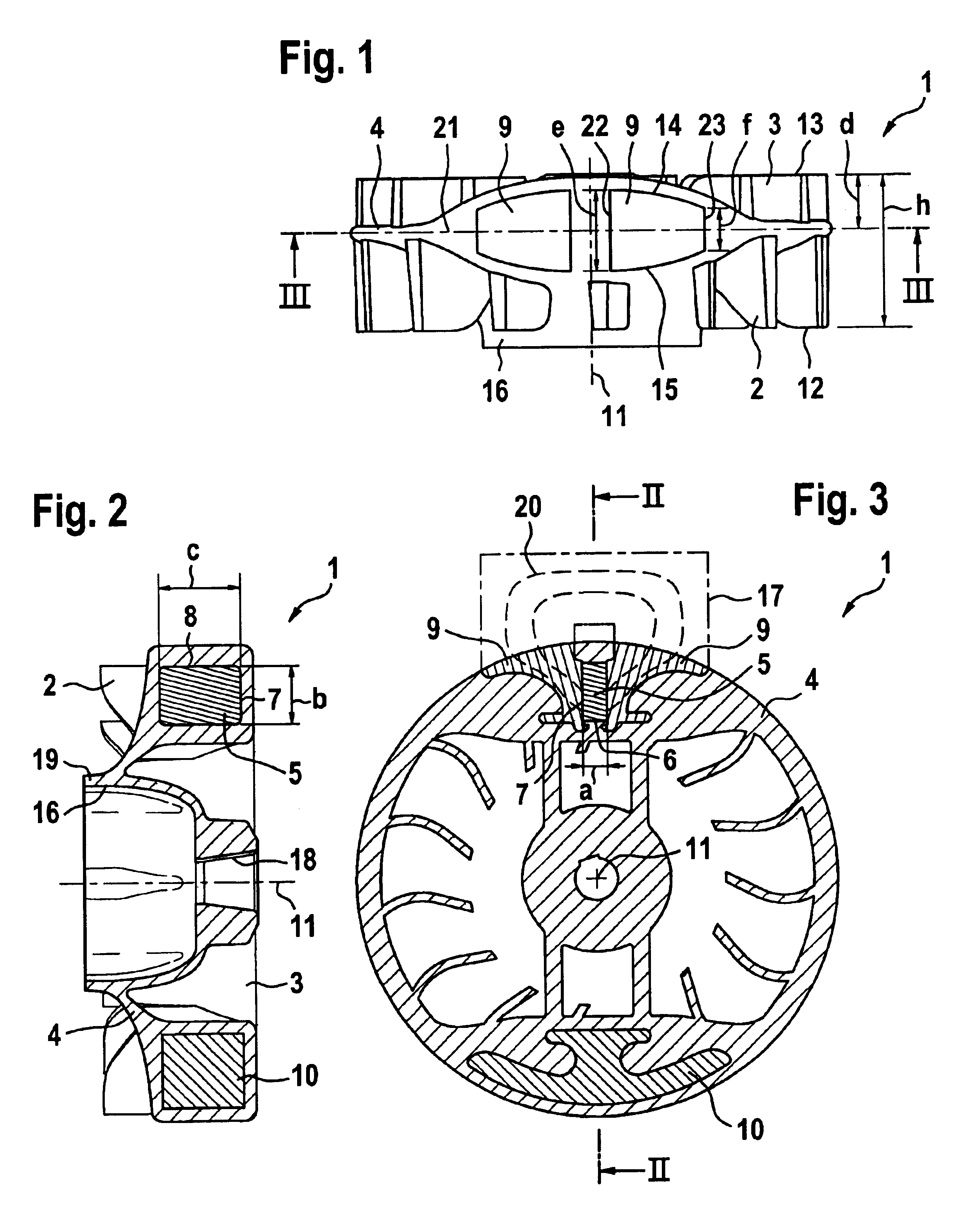
[0014]FIGS. 1 to 3 show a flywheel 1 for mounting on an internal combustion engine. The internal combustion engine is especially a two-stroke engine in a portable handheld work apparatus such as a motor-driven chain saw, cutoff machine or the like.

[0015]The flywheel is configured to be substantially rotationally symmetrical to a rotational axis 11. The flywheel 1 is fixed to the crankshaft of the internal combustion engine with the receptacle 18 shown in FIG. 2. Fixation takes place with fastening means, for example, a nut which is mounted over the opposite-lying receptacle 16. The receptacle 16 is configured to have a pot-like shape and is open on the front side 12 of the flywheel 1. The front side 12 is the side facing away from the engine; whereas, the rearward side 13 faces toward the engine. The receptacle 18 is open toward the rearward side 13.

[0016]The flywheel 1 has a partition wall 4 which is fixed to the edge 19 of the receptacle 16 and extends outwardly up to the peripher...


PUM


Abstract

A flywheel (1) for an internal combustion engine is provided for generating a cooling air flow and is especially for a two-stroke engine on a portable handheld work apparatus such as a motor-driven chain saw, cutoff machine or the like. The flywheel (1) carries a parallelopipedly-shaped permanent magnet (5) for a magnetic ignition system. The permanent magnet has a short edge (6), a center edge (7) and a long edge (8). The permanent magnet (5) is polarized in the direction of the short edge (6). To provide a high moment of inertia of the flywheel (1) while achieving a low weight, the short edge of the permanent magnet (5) runs tangentially to the peripheral direction of the flywheel (1) and that the long edge (8) of the permanent magnet (5) is aligned parallel to the rotational axis (11) of the flywheel (1).

Description

CROSS REFERENCE TO RELATED APPLICATION[0001]This application claims priority of German patent application no. 103 08 428.2, filed Feb. 27, 2003, the entire content of which is incorporated herein by reference.FIELD OF THE INVENTION[0002]The invention relates to a flywheel for an internal combustion engine including a two-stroke engine in a portable handheld work apparatus such as a motor-driven chain saw, cutoff machine or the like.BACKGROUND OF THE INVENTION[0003]Flywheels of this kind are provided with vanes for cooling the engine and are generally known. The flywheel is intended to compensate for rpm fluctuations of the engine. For this purpose, a high moment of inertia of the flywheel is advantageous. At the same time, the overall weight of the flywheel should, however, be as low as possible especially in two-stroke engines in portable handheld work apparatus such as motor-driven chain saws, cutoff machines or the like. A magnet for a magnetic ignition system is usually integrat...

Claims


Application Information

Patent Timeline
Patent Type & Authority Patents(United States)
IPC IPC(8): F02B75/00F02P1/00F02P1/02F02B75/06F16F15/30F01P5/02F02B63/02F02B63/00
CPCF02B75/06F02P1/02F16F15/302F01P5/02F02B63/02
Inventor HEINZELMANN, GEORG
Owner ANDREAS STIHL AG & CO KG
Why Eureka
Try Eureka