Device For Varying The Control Times Of An Internal Combustion Engine

Inactive Publication Date: 2009-05-14
SCHAEFFLER KG
View PDF4 Cites 6 Cited by
  • Summary
  • Abstract
  • Description
  • Claims
  • Application Information

AI Technical Summary

Benefits of technology

[0025]This measure likewise leads to a considerable weight r

Problems solved by technology

On account of the solid design of the swashplate, said

Method used


Image

  • Device For Varying The Control Times Of An Internal Combustion Engine
  • Device For Varying The Control Times Of An Internal Combustion Engine
  • Device For Varying The Control Times Of An Internal Combustion Engine

Examples


second embodiment

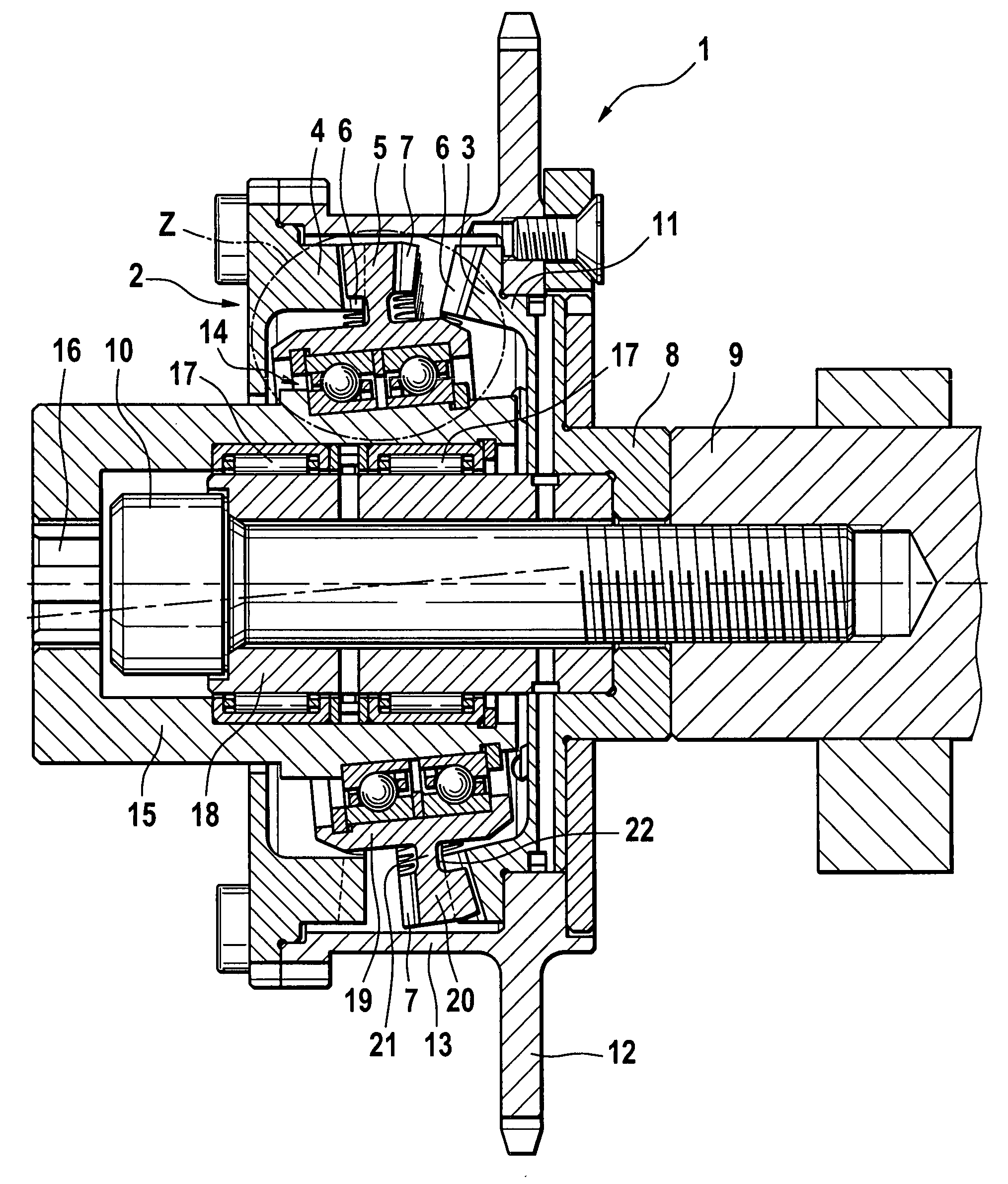
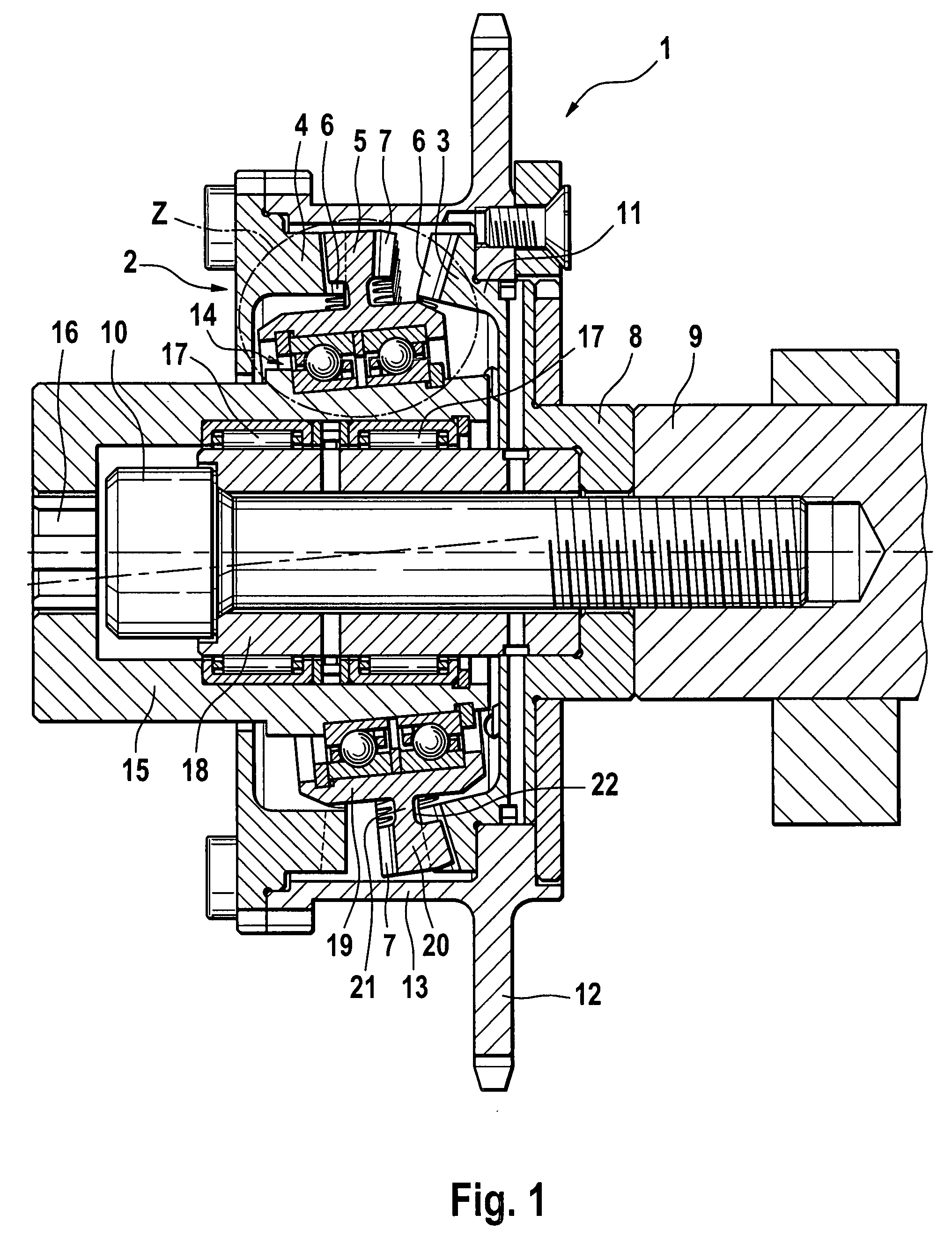
[0045]The toothing of the toothing part 20 extends, in FIG. 2a, proceeding from the radially outer edge of the swashplate 5 in the direction of the hub part 19, with the toothing not running out in the hub part 19. Moreover, an annular gap 22 is provided between the radially inner end of the toothing and the hub part 19. FIG. 2b shows, similarly to FIG. 2a, the detail Z of a second embodiment according to the invention of a device 1. The components are largely identical. However, the toothing of the two second toothed rims 7 runs out in the hub part 19. No annular gap 22 is provided here between the radially inner end of the toothing and the hub part 19. It is likewise conceivable for the teeth of only one toothed rim 7 to run out in the hub part 19. On account of the toothing, which merges into the hub part 19, of the second toothed rims 7, the bending resistance moment of the swashplate 5 is increased. The swashplate 5 can, for the same bending resistance moment, be of narrower de...

third embodiment

[0048]FIG. 3b shows a plan view, along the arrow III, of the swashplate 5 which is used in a third embodiment according to the invention of the device 1. In this embodiment, the teeth 23 are of hollow design. Each spacewidth 24 of a second toothed rim 7 simultaneously forms a tooth 23 of the other toothed rim 7 and vice versa. This can for example be obtained by the adaptation of the casting mold in the case of plastic swashplates 5, by adapting the pressing tool when using sintered steel or by forcing through the teeth 23 from a disk-shaped base body. It is possible in this way for swashplates 5 to be produced cost-effectively for example by means of non-cutting shaping of a sheet metal part. In comparison to the embodiment of FIG. 3a, the embodiment illustrated in FIG. 3b is lighter and is shorter in the axial direction.

[0049]The use of the toothing illustrated in FIG. 3a is of course not restricted to the second toothed rims 7 of the swashplate 5. Moreover, a similar design of th...


PUM


Abstract

The invention relates to a device (1) for varying the control times of an internal combustion engine (100), having a driving wheel (12), a driven element (8) and a swashplate mechanism (2). The torque of a crankshaft (101) is transmitted by means of a primary drive to the driving wheel (12) and further by means of the swashplate mechanism (2) to the driven element (8) which is connected fixedly in terms of rotation to a camshaft (9).
The swashplate mechanism (2) is composed of at least one bevel wheel (3) and a swashplate (5) which is mounted on an adjusting shaft (15).
It is the aim of the invention to reduce the mass and the installation space of the device (1).

Description

FIELD OF THE INVENTION[0001]The invention relates to a device for varying the control times of an internal combustion engine according to the respective preamble of patent claims 1, 4 and 6.BACKGROUND OF THE INVENTION[0002]In internal combustion engines, camshafts are used for actuating the gas exchange valves. Camshafts are mounted in the internal combustion engine in such a way that cams attached to them bear against cam followers, for example bucket tappets, drag levers or rocker arms. When the camshaft is set in rotation, the cams roll on the cam followers which in turn actuate the gas exchange valves. Both the opening duration and amplitude but also the opening and closing time point of the gas exchange valves are defined by the position and shape of the cams.[0003]Modern engine concepts tend toward a variable design of the valve drive. On the one hand, the valve stroke and valve opening duration are to be capable of being configured variably up to the complete cut-off of indiv...

Claims


Application Information

Patent Timeline
IPC IPC(8): F01L1/352
CPCF01L1/022F01L1/024F01L1/026F16H1/321F01L2101/00F01L2103/00F01L2820/032F01L1/352F01L2301/00F01L2303/00
Inventor SCHAFER, JENSKOHRS, MIKE
Owner SCHAEFFLER KG
Why Eureka
Try Eureka