Wind Turbine Assembly

a technology of wind turbines and components, applied in wind turbines, motors, sustainable buildings, etc., can solve the problems of automatic limitation of output torque at extremely high wind speeds, and achieve the effect of enhancing air flow diffusion and enhancing concentration of air flow to the rotor

Inactive Publication Date: 2015-01-15
THE POWER COLLECTIVE INC
View PDF8 Cites 7 Cited by
  • Summary
  • Abstract
  • Description
  • Claims
  • Application Information

AI Technical Summary

Benefits of technology

[0027]The rotor housing may have an inlet air deflection slat configured to channel air flow incident into the rotor away from the support. Advantageously, such a slat may enhance concentration of the air flow to the ro

Problems solved by technology

Advantageously, the output torque at extremely high wind speeds may be automatically limi

Method used


Image

  • Wind Turbine Assembly
  • Wind Turbine Assembly
  • Wind Turbine Assembly

Examples


Embodiment Construction

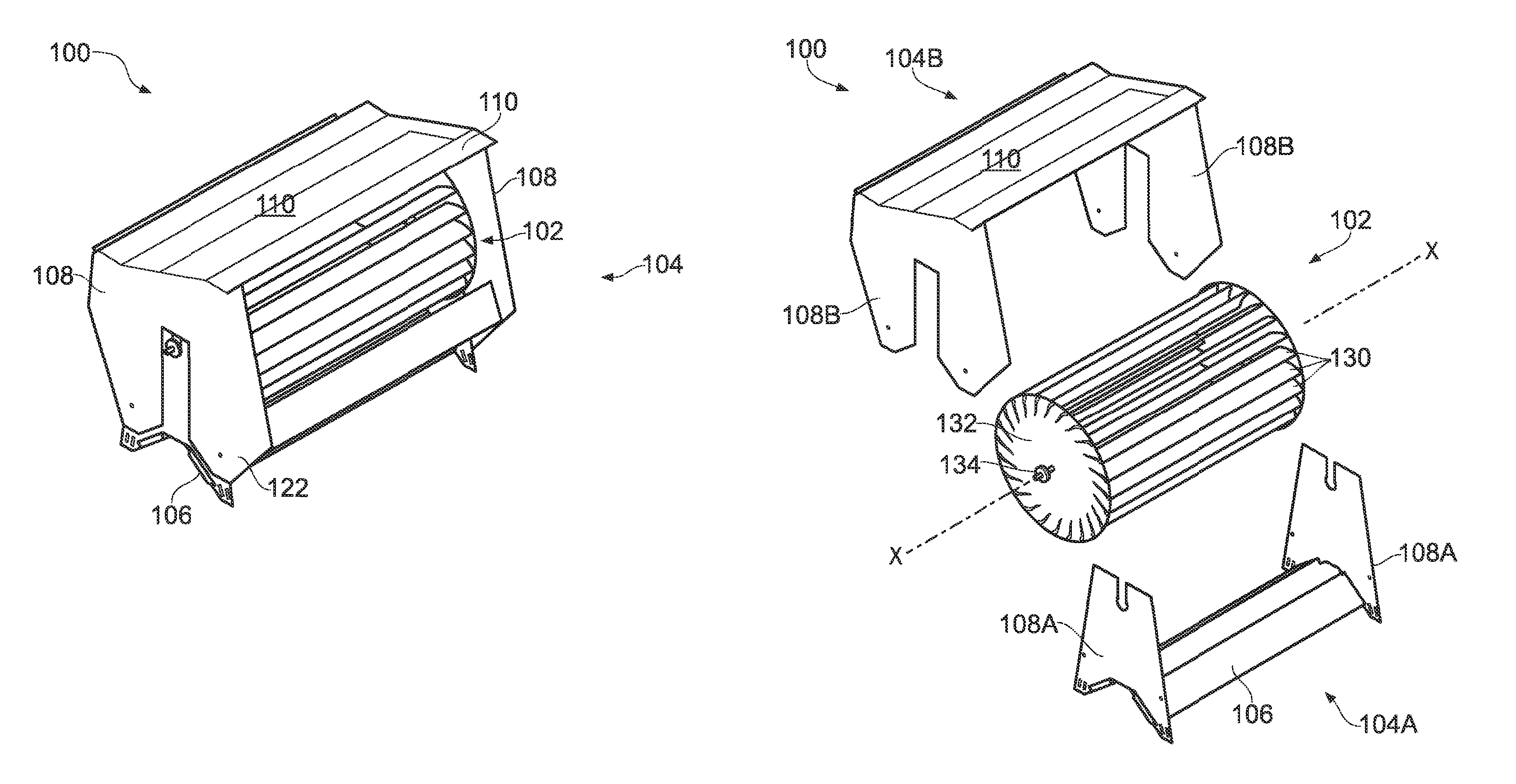
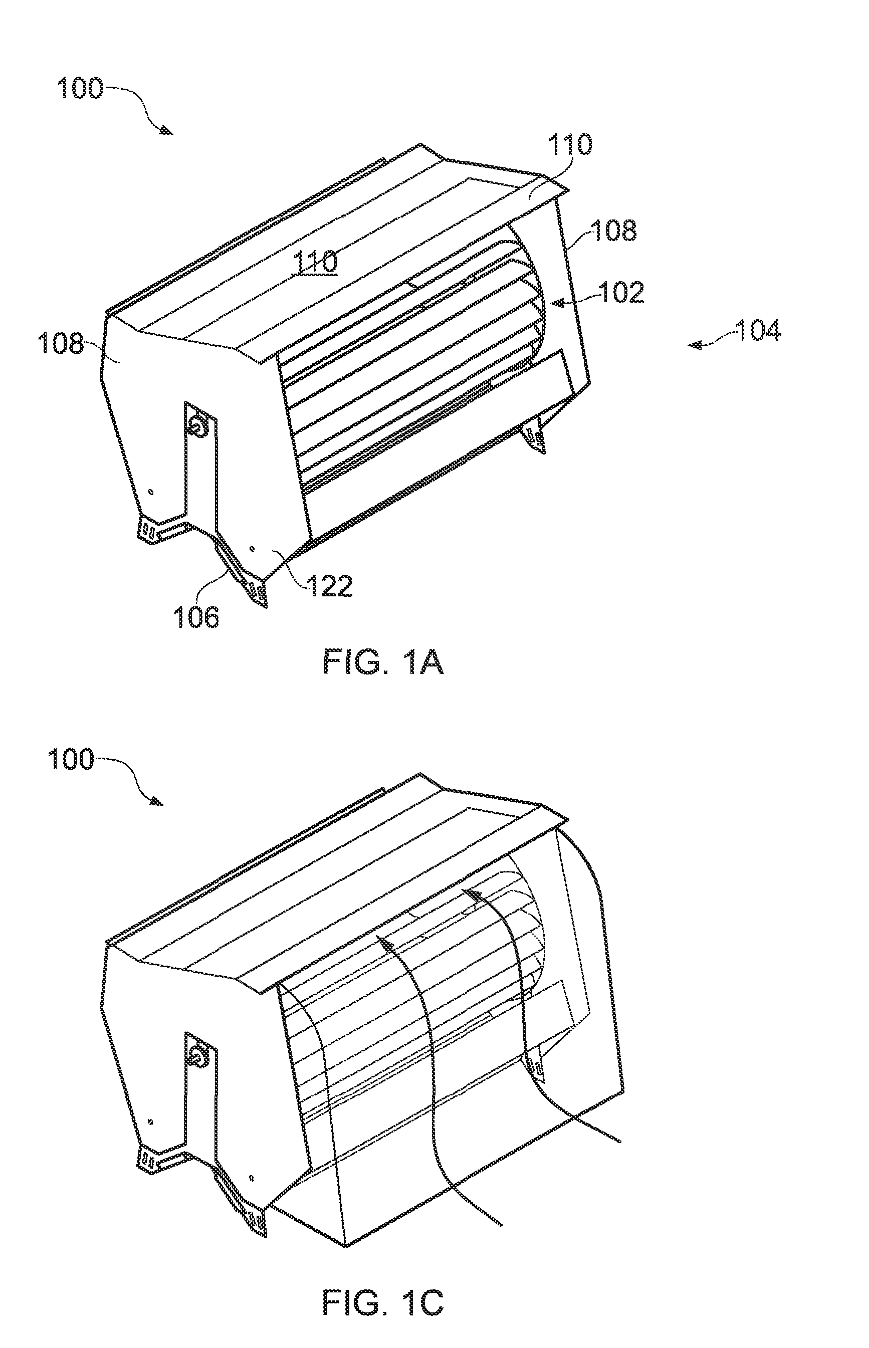
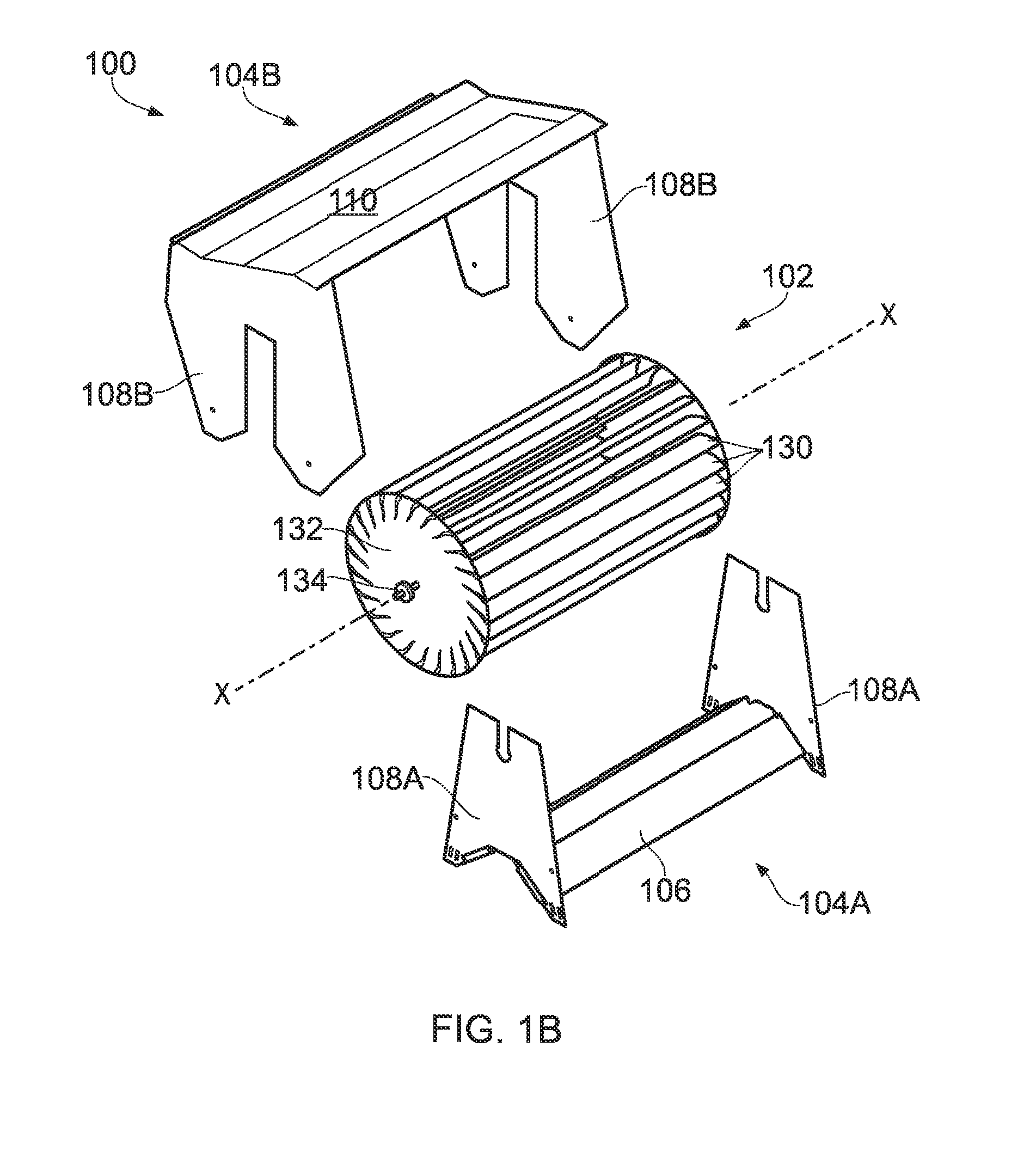
[0037]Like reference numerals refer to like elements throughout, albeit in some cases having one or more suffix letters. For example, in different figures, 108, 108A and 108B have been used to indicate an end panel and its component parts, and similarly 130, 130A and 130B have been used to indicate aerofoil blades in general and two blades in particular.

[0038]FIGS. 1A to 1D show views of a wind turbine assembly 100 comprising an elongate generally cylindrical wind turbine rotor 102 rotatably mounted within a housing 104.

[0039]The housing 104 comprises a base section 106, end panels 108 and a cover 110. Conveniently, the housing 104 can be disassembled into lower and upper housing parts 104A and 104B, such that the lower housing part, rotor 102 and upper housing part may be separately and successively installed onto a roof. The end panels have a composite construction, with component parts 108A and 108B provided by the upper and lower housing parts 104A and 104B.

[0040]The lower housi...


PUM


Abstract

A wind turbine assembly comprising a generally cylindrical wind turbine rotor that is supported by a rotor support and operable to rotate about a rotational axis, the rotor comprising a plurality of aerofoil blades with each aerofoil blade having a leading edge, a trailing edge, a suction surface, a pressure surface, and an aerofoil chord having a chord length between the leading edge and the trailing edge, the aerofoil blades being in a generally cylindrical arrangement around the rotational axis with the leading edges at a larger radial separation from the rotational axis than the trailing edges, and the chords being angled relative to radii through the rotational axis such that the suction surfaces and pressure surfaces respectively face generally outwardly and inwardly from and to the rotational axis, wherein the minimum separation (S) between the leading edge of a first aerofoil and the suction surface of an adjacent aerofoil is less than the chord length (LC), and wherein the location of the maximum thickness of each aerofoil blade (LTmax) along the chord (LC)) is less than 20% of the chord length (L) from the leading edge.

Description

[0001]The present invention relates to a wind turbine assembly having a generally cylindrical wind turbine rotor, and more particularly such a wind turbine assembly that is supported within a rotor housing.BACKGROUND[0002]A known design of wind turbine has a tower-mounted propeller-like rotor, typically comprising two or three blades that radiate perpendicular to the axis of rotation of the rotor, which is generally aligned with the prevailing wind direction. Other known designs of wind turbine have blades arranged in a frame or cage and the blades extend along the axis of rotation of the rotation, which is aligned transverse to the prevailing wind direction. Examples of the latter are Savonius rotors or Darrieus rotors, as described in U.S. Pat. No. 1,697,574 and U.S. Pat. No. 1,835,018 respectively, as well as a basic paddle-wheel type of rotor.[0003]Wind turbines are typically designed to maximise their power output in relatively high wind speed conditions. However, under substan...

Claims


Application Information

Patent Timeline
IPC IPC(8): F03D3/06F03D11/00
CPCF03D11/00F03D3/061F03D3/002F03D3/0427F03D9/34F03D13/20F03D80/00F05B2240/231F05B2240/301F05B2240/9112Y02B10/30Y02E10/728Y02E10/74
Inventor KEECH, WINSTON DONALD
Owner THE POWER COLLECTIVE INC
Why Eureka
Try Eureka