
Brain retraction sensor

a brain retraction and sensor technology, applied in the field of intracranial sensors, can solve the problems of brain retraction, brain injury, and difficulty for surgeons to accurately gauge the amount of pressure actually applied to the brain, and achieve the effect of reducing brain retraction injury

Inactive Publication Date: 2005-07-12
AYAD MICHAEL
View PDF26 Cites 25 Cited by
  • Summary
  • Abstract
  • Description
  • Claims
  • Application Information

AI Technical Summary

Benefits of technology

[0021]A device is disclosed comprising an inextensible pressure distribution means (e.g., elastomer grid) that allows for redistribution of pressure along the surface of the brain when said device is in contact with said organ. It is an object of this invention that when

Problems solved by technology

Unfortunately, it is very difficult for the surgeon to accurately gauge the amount of pressure actually applied to the brain during such placement of the retractor (see, e.g., Hongo et al., J Neurosurg 1987; 66:270-275).
Moreover, it is also possible to inadvertently position the blade of the retractor such that a focal pressure point occurs at one particular area of the retractor blade pressing against the brain.
Thus, injury to the brain can occur as a result of brain retraction when either the force applied is excessive or when the pressure is not adequately distributed to a large enough area of brain.
Various attempts have been made to develop technology to help minimize the incidence of this type of injury, with limited success.
This approach has limited utility because pressure can only be measured from the point or points where the strain gauges are situated.
Certainly this technique does little, if anything, to distribute force on the brain more evenly.
Because of this, electrodes can only be placed to the extent that they do not interfere with the sterile surgical field, and obviously cannot be placed in the area of the craniotomy.
Unfortunately, this method often reports erroneously favorable information that does not reflect the injury developing at the retractor site.
Such high doses cause suppression of both the EEG and SSEP, thus rendering them ineffective for the detection of imminent brain injury.
However, with the exception of the clinical study currently investigating the device described herein, the benefits of DC potential for monitoring brain injury intraoperatively have not been put to use.
This is, no doubt, because a practical method for applying the electrodes to relevant parts of the brain without obscuring the operative field has not been available.
Stainless steel and other electrodes are unsatisfactory because ion deposition at the brain-electrode interface causes artifactual potentials which prevents registration of the true voltage signal.
However, such devices do not allow for monitoring of intracranial pressure.
Currently, there is no technology available to record electrical activity from areas of the brain that are being retracted.
With respect to monitoring retra

Method used


Image

  • Brain retraction sensor
  • Brain retraction sensor
  • Brain retraction sensor

Examples


example i

[0131]A series of experiments was carried out in anesthetized New Zealand white rabbits in order to evaluate the function of the BRS. Rabbits were placed in a stereotactic head frame, and a temporo-parietal craniotomy was performed using a high-speed surgical drill. Using a retractor blade with BRS mounted to a micromanipulator, groups of animals underwent medially-directed retraction of the lateral temporal lobe at an initial pressure of 20, 30 or 40 mm Hg, as gauged by the device, for either 15 or 30 min. Electrocorticogram (ECoG), which refers to EEG taken directly from the cortical surface rather than scalp, along with cortical DC potential and retraction pressure were recorded on a Bio-logic digital polysomnographic monitor during the retraction period and for 8 hours post-injury. The latter two modalities were amplified via a battery-powered Iso-Dam® high-input impedance DC amplifier (World Precision Instruments, Sarasota, Fla.) and catheter strain gauge with bridge amplifier ...


PUM


Abstract

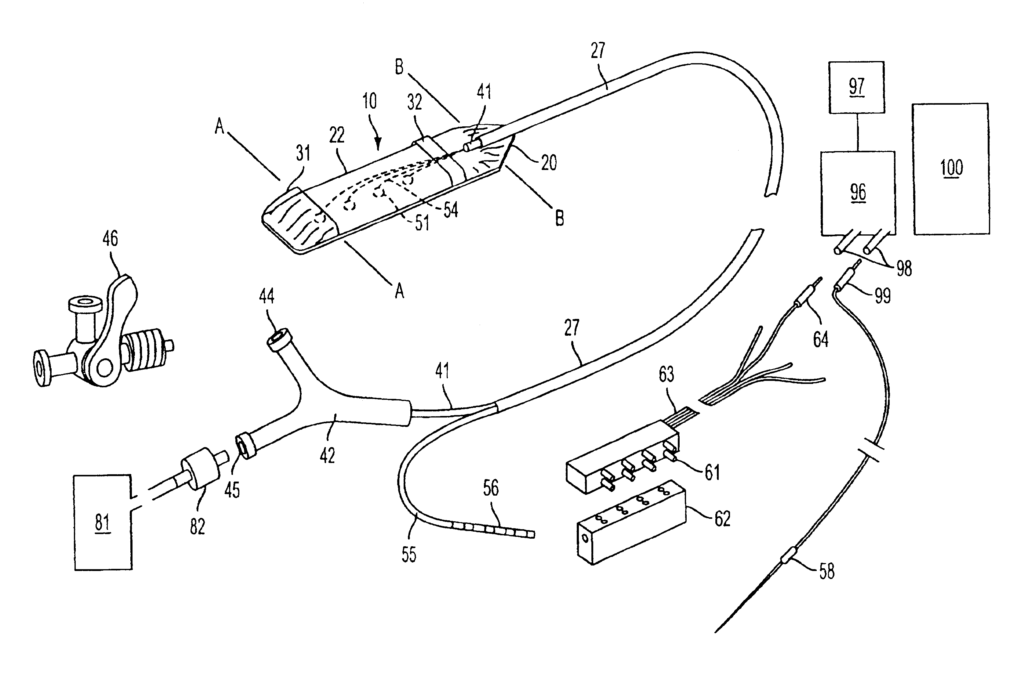
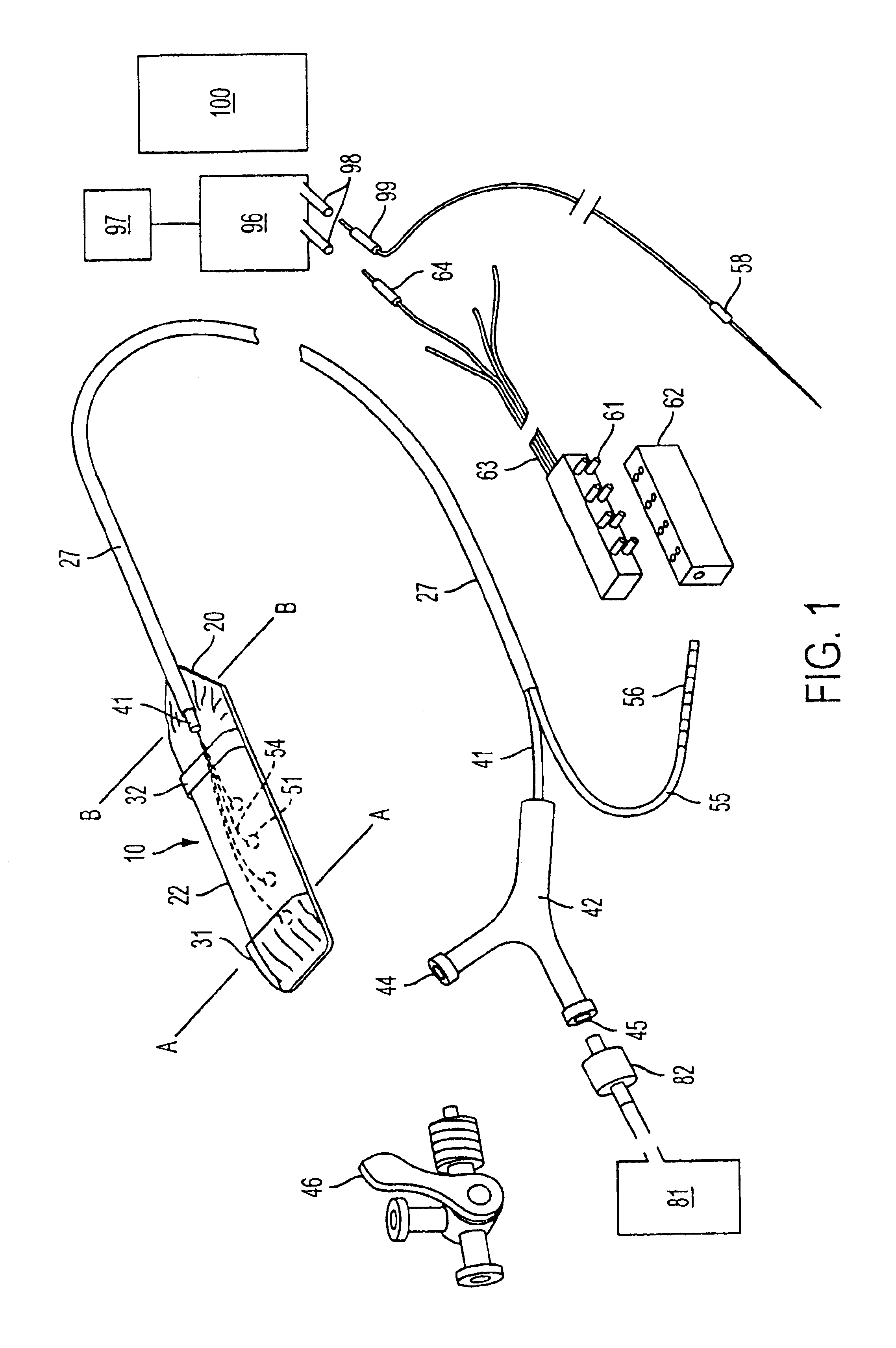
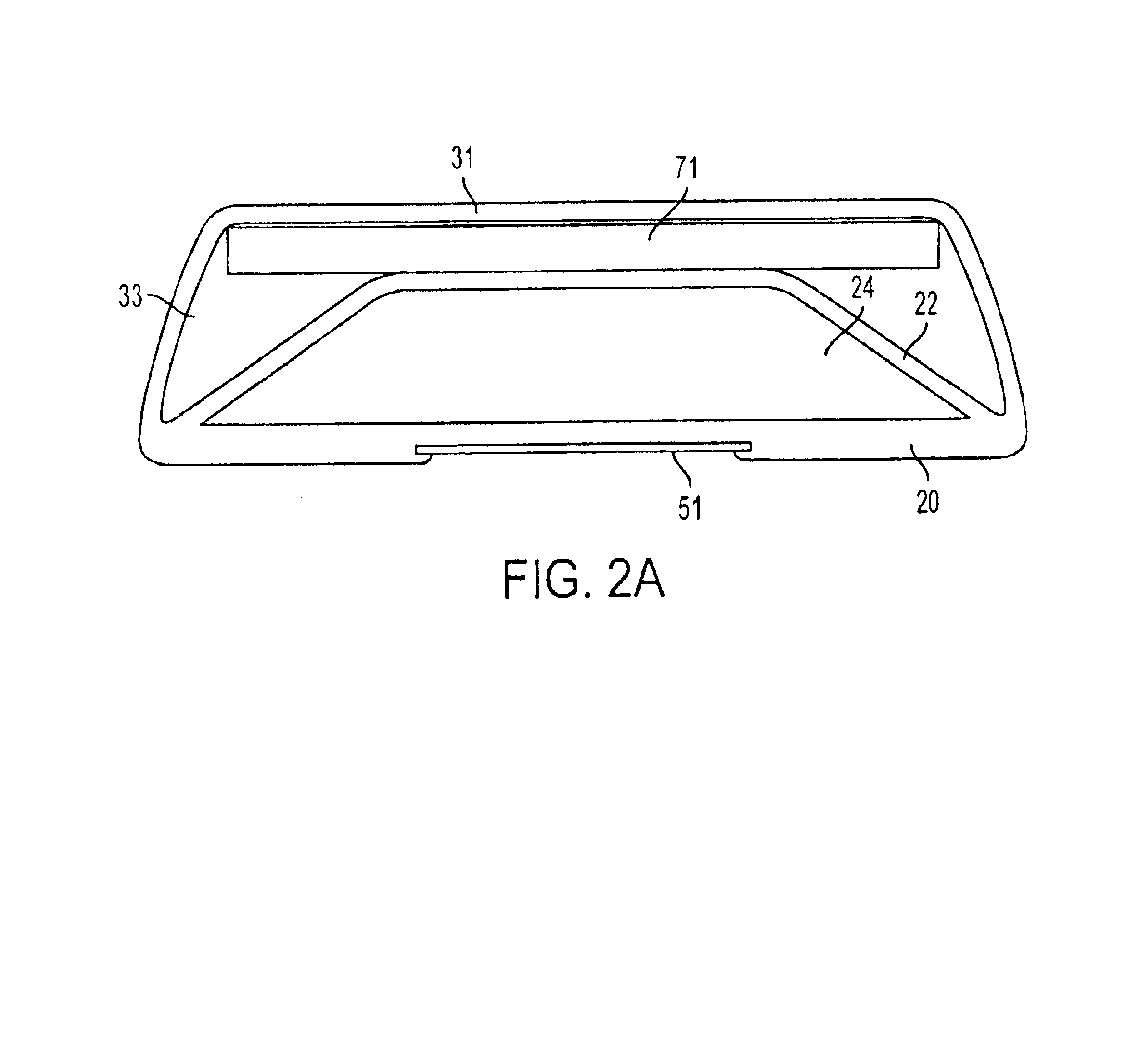
An electrode grid device is disclosed comprising a deformable envelope, further comprising non-polarizable electrodes and a pressure recording port. The device is designed to allow for monitoring of brain retraction pressure and local cortical electrical activity including DC potential, as well as to redistribute the force applied during retraction and thereby diminish the chance of focal brain injury during surgery. Retraction pressure recorded is equal over the full area of contact, providing a more meaningful measurement than simply at one point on the retractor. A means is disclosed for evacuation of air from the system to improve accuracy and fidelity of the pressure measurements. It is a further aspect of the device to allow for measurement of intracranial pressure, DC potential and EEG in epileptic and severe head trauma patients for management of edema and injury, respectively.

Description

FIELD OF THE INVENTION[0001]This invention is related generally to intracranial sensors for prevention of retractor blade injury (i.e., “retraction injury”) of the brain, and subdural monitoring devices.BACKGROUND[0002]A retractor is an instrument used during surgery for, among other things, holding back structures adjacent to the immediate operative field (See, e.g., U.S. Pat. No. 5,769,781). During neurosurgical operations for aneurysms, tumors or other lesions located in the skull base, the surgeon must employ retracting devices in order to displace one or more lobes of the brain enough to gain adequate surgical exposure to the lesion. These retractors are adjusted by hand to optimize exposure. Unfortunately, it is very difficult for the surgeon to accurately gauge the amount of pressure actually applied to the brain during such placement of the retractor (see, e.g., Hongo et al., J Neurosurg 1987; 66:270-275). Moreover, it is also possible to inadvertently position the blade of ...

Claims


Application Information

Patent Timeline
IPC IPC(8): A61B5/03A61B5/0476A61B5/0478
CPCA61B5/031A61B5/0478A61B5/4076A61B2562/0215A61B5/291
Inventor AYAD, MICHAEL
Owner AYAD MICHAEL
Learn More